

User Manual – Rev J
CS Series
California Instruments
62
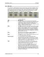
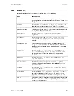
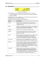
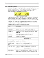
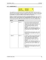
ENTRY
DESCRIPTION
information.
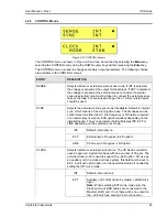
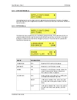
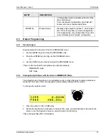
MODE
Power on clock mode. The following two modes can be selected.
STAND
Power up in INT (internal) clock mode for stand-
alone operation. This is the only mode for CS unit
without the –LKS option.
For units with the –LKM option installed, this field is
fixed to CLK/LOCK.
For units with the –LKS option installed, this field
can be changed to CLK/LOCK for use as an
auxiliary unit in a clock and lock system or to
STAND for use as a stand alone unit.
CLK/LOCK
Fixed on master (-LKM) unit configuration in a clock
and lock system. Power up with EXT (external)
clock mode on unit with –LKS option. (See OPTION
menu section.).
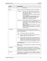
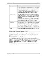
Note
that this field cannot be changed if the –LKM
option is installed.
The frequency resolution below 81.9 Hz in MAST
clock and lock mode is reduced to 0.1 Hz from the
normal 0.01 Hz.
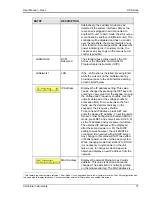
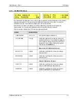
ALC STATE
Sets the Auto Level Control (ALC) mode. This mode uses the
internal measurement system to zero regulate the output. There are
three modes of operation:
OFF No measurement based output regulation.
REG Output regulation is enabled. AC source will continuously
regulate output but will not trip off output.
ON
Output regulation is enabled and output will fault (trip off)
with Error 802 “Output current fault” if regulation cannot be
maintained and the programmed output current is 100 mA
or higher. No error is generated for settings below 100 mA.
In most situations, the ALC mode should be set to REG or ON for
optimal performance.
Note:
The ALC mode only functions for programmed output currents
above 100 mA.
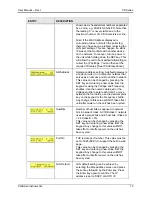
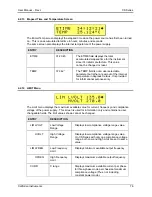
CURR REF
Selects internal or external current programming. Select INT for
programming of current from the front panel or over the bus. Select
EXT to use the RPV (remote programming current). The RPV input
expects a 0 to +10 Vdc signal for 0 to full-scale current.
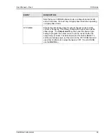
NO OUTP
Selects SINGLE or THREE phase mode of operation. In SINGLE-
phase mode, all current is delivered to the øA and COM terminals of
the OUTPUT terminal block.
Содержание 13500CS/3
Страница 5: ...User Manual Rev J CS Series California Instruments 5 SAFETY SYMBOLS ...
Страница 34: ...User Manual Rev J CS Series California Instruments 34 Figure 3 3 9000CS 2 Wiring diagram 3 Phase mode ...
Страница 35: ...User Manual Rev J CS Series California Instruments 35 Figure 3 4 13500CS 3 Wiring diagram 3 Phase mode ...
Страница 36: ...User Manual Rev J CS Series California Instruments 36 Figure 3 5 18000CS 4 Wiring diagram 3 Phase mode ...
Страница 56: ...User Manual Rev J CS Series California Instruments 56 The power source is now ready to be used ...
Страница 73: ...User Manual Rev J CS Series California Instruments 73 ...
Страница 111: ...User Manual Rev J CS Series CS Series 111 voltage rating 28 W Weight 22 Wiring AC input 30 ...