User Manual – Rev J
CS Series
California Instruments
49
4. Front Panel Operation
4.1
Tour of the Front Panel
Before operating the AC source using the front panel, it helps to understand the operation of the
front panel controls. Specifically, the operation of the knob, keyboard and the menu layout are
covered in the next few paragraphs.
4.1.1
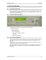
Front Panel Controls and Indicators
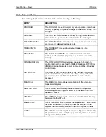
The front panel can be divided in a small number of functional areas:
•
Mains circuit breaker
•
Keyboad/ Display panel:
•
Status Indicator lights
•
Shuttle knobs (Voltage / Frequency)
•
LCD
display
•
MENU and CURSOR keys
4.1.2
System On/Off Circuit Breaker
The circuit breaker located on the top left side of the front panel of the unit and disconnects the
three phase Line input. As such, the circuit breaker acts as a power on/off switch for the CS
Series unit.
When the input current rating of the CS Series AC power source is exceeded or an input over
voltage condition occurs, the circuit breaker will trip.
Note that for multi-chassis systems, it is recommended to turn the Master unit ON first and then
the Auxiliary unit(s). To turn the system off, turn OFF the Auxiliary unit(s) first and then the
Master unit.
Содержание 13500CS/3
Страница 5: ...User Manual Rev J CS Series California Instruments 5 SAFETY SYMBOLS ...
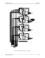
Страница 34: ...User Manual Rev J CS Series California Instruments 34 Figure 3 3 9000CS 2 Wiring diagram 3 Phase mode ...
Страница 35: ...User Manual Rev J CS Series California Instruments 35 Figure 3 4 13500CS 3 Wiring diagram 3 Phase mode ...
Страница 36: ...User Manual Rev J CS Series California Instruments 36 Figure 3 5 18000CS 4 Wiring diagram 3 Phase mode ...
Страница 56: ...User Manual Rev J CS Series California Instruments 56 The power source is now ready to be used ...
Страница 73: ...User Manual Rev J CS Series California Instruments 73 ...
Страница 111: ...User Manual Rev J CS Series CS Series 111 voltage rating 28 W Weight 22 Wiring AC input 30 ...


