background image


233  


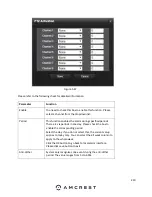
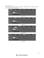
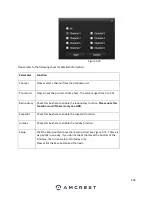
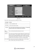
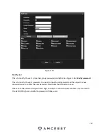
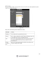
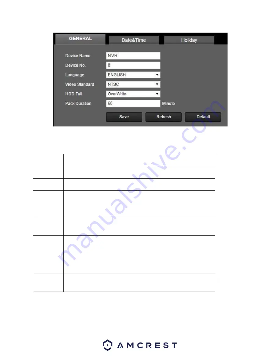
Figure 5-86  

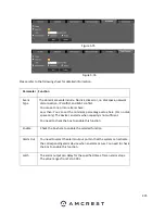
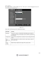
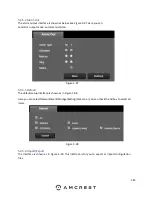
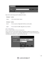
Please refer to the following sheet for detailed information.      


Parameter  


Function  


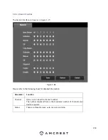
Device ID     

This is to set device name.      

Device No.       This is device channel number.      

Language      You can select the desired language from the dropdown list.  

Please note 

the device needs to reboot to activate this modification.  


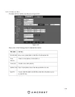
Video     

Standard     

This is to set the display video standard such as PAL.     
     

HDD full     

Here is where you to select the working mode when the hard disk is full. 
There are two options: stop recording or rewrite. If the NVR is in rewrite 
mode, the current working HDD is full, and the next HDD is not empty, 
the oldest files will be overwritten. If the NVR is in stop recording mode, 
the HDD is full, and the next HDD is not empty, recording will stop.     

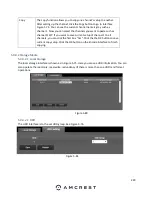
Pack  duration     

Here is where you to specify the recording duration. The value ranges 
from 1 to 120 minutes. Default value is 60 minutes.      

Содержание NV21 Series

Страница 1: ...Network Video Recorder User Manual Version 1 0 4 Revised November 21st 2018 ...

Страница 2: ...specifications 16 2 4 Audio Ports 17 2 5 Mouse Operation 18 3 Device Installation 19 3 1 Check Unpacked NVR 19 3 2 HDD Installation 19 3 3 Setting Up Cable Connections 21 4 Local Basic Operation 26 4 1 Boot up and Shutdown 26 4 1 1 Boot up 26 4 2 Startup Wizard Walkthrough 27 4 2 1 General 31 4 2 2 Network 32 4 3 Preview 35 4 3 1 Preview Control Interface 36 4 3 3 Right Click Menu 38 4 3 3 1 1 PTZ...

Страница 3: ...B Manager 60 4 3 4 18 Upgrade 61 4 5 Main Menu Overview 61 Settings Menu 62 4 6 Camera 62 4 6 1 Remote 62 4 6 1 1 Device Status 65 4 6 1 2 Firmware 66 4 6 1 3 Update 67 4 6 2 Camera 68 4 6 3 Audio Video 71 4 6 3 3 Overlay 73 4 6 5 Channel Name 75 4 7 Network 75 4 7 1 TCP IP 75 4 7 2 Connection 77 4 7 3 PPPoE 79 4 7 4 DDNS 79 4 7 5 UPNP 81 4 7 8 FTP Setting 85 4 8 Event 93 4 8 1 Detect 93 4 8 2 Ala...

Страница 4: ... 140 4 15 Network 142 4 15 1 Online Users 142 4 15 2 Net Load 142 4 15 3 Network Test 143 4 16 Log 144 Below is a description of the items listed in this field 145 4 16 1 Backup 146 Operation Menu 146 4 17 Search 146 4 19 Shutdown 158 5 Web Operation 159 5 1 General Introduction 159 5 1 1 Preparation 159 5 1 Local Web Access 161 5 2 Remote Web Access 162 5 2 1 UPnP DDNS Remote Access Setup 163 5 2...

Страница 5: ...2 Log 245 5 10 3 Online User 246 5 11 Playback 247 5 12 Alarm 250 5 13 Logout 251 5 14 Un install Web Control 251 Amcrest View Web Portal Setup 252 6 1 Installing the AmcrestView com browser plugin 252 6 2 User Method 256 7 3 Device method 263 6 4 Amcrest View Web Interface Overview 265 FAQs Troubleshooting 268 Glossary 273 FCC Statement 274 IC Warning Statement 275 Appendix A Toxic or Hazardous M...

Страница 6: ... are not allowed during transportation storage or installation 3 Installation Always keep the device upright and handle with care Do not apply power to the device before completing the installation Do not place objects on the NVR 4 Qualified Engineers Needed All examinations and repair work should be done by qualified service engineers We are not liable for any problems caused by unauthorized modi...

Страница 7: ...VR systems 1 Overview and Features 1 1 Overview This is a high performance network video recorder The device supports local preview multiple window display local storage of recordings mouse shortcut menu operations and remote management This device supports central storage front end storage and client end storage The monitor zone in the front end can be setup anywhere Working with other front end ...

Страница 8: ...ding setup such as alarm and schedule setups you can backup related audio video data on the device Supports web recording via a web user interface local recording and storing files on the client end Alarm Responds to external alarms simultaneously within 200MS and based on the user s predefined relay setup the system can process the alarm input and prompt the user by screen and voice supports prer...

Страница 9: ...heral USB 2 0 device etc Network Management Supervise NVR configurations and control power via Ethernet Supports management via a web interface Peripheral Equipment Management Supports peripheral equipment management such as protocol setup and port connection Supports transparent data transmission such as RS232 RS 422 RS485 RS 485 Auxiliary Supports switching between NTSC and PAL Supports real tim...

Страница 10: ...rk error occurs or there is no network connection the light becomes red to alert you 6 ACT Remote control indicator light When the NVR receives a signal from the remote the light will blink 7 POWER Power indicator When NVR is on the light is on 8 ESC ESC Go to previous menu or cancel current operation When playback click it to restore real time monitor mode 9 FN Assist One window monitor mode clic...

Страница 11: ...uilt in CD drive if applicable Power button Power button press this button for three seconds to boot up or shut down NVR Shift Shift In textbox click this button to switch between numeral English Small Capitalized donation etc Up 1 Down 4 Activate current control modify setup and then move up and down Increase decrease numeral Assistant function such as PTZ menu In text mode input number 1 4 Engli...

Страница 12: ...is light turns red PWR Power indicator When NVR is on this light remains on HDD HDD abnormal indicator light When an HDD error occurs or the HDD capacity is below the specified threshold value this light turns red 2 2 Rear Panel The rear panel of the NVR may differ model to model Below is a representation of the rear panel of all applicable NVR devices NVXXXX Series is shown below NV4432 Series is...

Страница 13: ...n video and multiple channel data to the HDMI port of the display device HDMI version is 1 4 VGA VGA video output port VGA video output port Outputs analog video signal This connects to the monitor to view analog video GND Ground end Power input port Power socket For NVXXX series inputs DC 12V 2A For NV4432 series inputs DC 48V 1 25A For NVR41H 8P series inputs DC 48V 2A MIC IN Audio input port Bi...

Страница 14: ...E PORT PoE port Built in switch Supports PoE For PoE series products you can use this port to provide power to the network cameras 2 3 Alarm Connection 2 3 1 Alarm Port The alarm port is shown as below See Figure 2 6 The following figure is based on the 78 series Figure 2 6 Icon Function 1 2 ALARM1 ALARM2 The alarm becomes activated in the low level NO C NO activation output On off button 12V Rate...

Страница 15: ...ice to the alarm input port ALARM IN 1 2 of the NVR Note When connecting the ground port of the alarm device to the NVR you can use any of the GND ports When there is peripheral power supplying the alarm device ensure it is grounded on the NVR 2 3 3 Alarm input and output port There is peripheral power supplying to the external alarm device An overload may result in NVR damage Please refer to the ...

Страница 16: ...0VDC Maximum switch current 1A Insulation Between contacts with same polarity 1000VAC 1minute Between contacts with different polarity 1000VAC 1minute Between contacts and winding 1000VAC 1minute Surge voltage Between contacts with same polarity 1500V 10 160us Length of open time 3ms max Length of close time 3ms max Longevity Mechanical 50 106 MIN 3Hz Electrical 200 103 MIN 0 5Hz Temperature 40ºC ...

Страница 17: ...e end speak via a microphone and then you can hear the audio through the headphones or speakers at the PC end 2 4 2 PC end to the device end Device Connection Connect a microphone to the audio input port in the PC and then connect headphones or speakers to the first audio input port in the device rear panel Login to the Web and then enable the corresponding channel real time monitor Please refer t...

Страница 18: ...you can select different input methods Left click the corresponding button on the panel to input a numeral English character small capitalized Here stands for backspace stands for space In English input mode _ stands for inputting a space icon and stands for deleting the previous character In numeral input mode _ stands for clear and stands for deleting the previous numeral Double left Implement s...

Страница 19: ...ion detection zone Select the privacy mask zone 3 Device Installation Note All the installation and operations here should conform to your local electric safety rules 3 1 Check Unpacked NVR When you receive the NVR system in the packaging unpack it and check all sides of the NVR for any physical damage The protective materials used in the packaging of the NVR can protect most accidental damage dur...

Страница 20: ...n an NVR must be no larger than 6TB Terabytes However larger NVRs such as the 32 channel NV4432E HS NV4432 HS etc can house up to a total of 4 hard drives inside the case Note When installing hard drives on any NVR each hard drive installed cannot exceed 6TB To install your hard drive the following is needed A medium sized regular Phillips head screwdriver not included A hard drive not included Fo...

Страница 21: ...nections there are 5 simple steps 1 Connect a monitor or TV screen to your NVR The NVR is compatible with any monitor or screen that uses a VGA or HDMI connection For purposes of this guide we will use a VGA connection Take a VGA cable and connect one end to the VGA port on your monitor screen and the other end to the VGA port on the back panel of your NVR 2 Connect an Ethernet cable to your route...

Страница 22: ... end of the Ethernet cable to the NVR 3 Connect the USB mouse to a USB port on the NVR 4 Connect your cameras a For PoE Cameras If you are using a PoE camera connect an Ethernet cable to the Ethernet port attached to the camera ...

Страница 23: ...cable to a PoE port on the back of the NVR Note PoE cameras can either be powered with a PoE connection or with a standard power adapter sold separately b For WiFi Cameras Connect the camera s power adapter to the power port attached to the camera ...

Страница 24: ...n take the power plug and connect it to the power brick on one end the power brick is shown in the image below and connect the other end of the power cable into a wall outlet or power strip The NVR will turn on Allow the device to boot up you will then be taken to an administrator setup page Note Your NVR may not work properly if the following is not accounted for ...

Страница 25: ...u will see the login screen appear On the monitor or TV please make sure the input is set to VGA 3 On your NVR open the Main Menu by left clicking once on the live feed screen and under the Settings row click on the System icon Then on the new window click Display from the list on the left column of options Change your resolution from 1280x1024 to 1920x1080 and click Apply down below Your NVR will...

Страница 26: ... ways for you to shut down the NVR a Main Menu RECOMMENDED From Main Menu Shutdown select shutdown from the dropdown list Click the OK button and the device shuts down The first screen you will be taken to during setup will be the Administrator page In this page you will set your NVR username and password as well as set up security questions These security questions will help assist during passwor...

Страница 27: ...or page has been modified you will then be taken to the startup wizard which will guide you through a step by step process of setting up your NVR 4 2 Startup Wizard Walkthrough The first page of the Startup Wizard will appear ...

Страница 28: ...mera s IP address to Static If the device does not have a static IP address assigned in the system there could be a compromise in the integrity of the connection if the NVR loses power or resets For more information on how to set a static IP for your camera visit amcrest com staticIP There are two ways for you to go to the smart add interface From the startup wizard click Smart add button On the p...

Страница 29: ...29 Now you can go to the smart add interface Click smart add button you can see device enables DHCP function ...

Страница 30: ...30 System pops up the following interface for you to confirm IP information if there are several IP segments Now you can see system is auto adding IPC to the corresponding channels ...

Страница 31: ...Startup and click Cancel Note Every page from the Startup Wizard that follows can be accessed and modified at any time through the Main Menu 4 2 1 General The first screen that comes up is the GENERAL settings screen Make sure to click the tabs at the top for Date Time as well as Holiday to configure those settings as well Once you are satisfied with the settings on this screen click the Next Step...

Страница 32: ...for your NVR on a laptop or PC For more information how to access the web user interface visit amcrest com NVRwebsetup Once you are satisfied with the settings on this screen click the Next Step button at the bottom of the screen 4 2 3 Remote Device The next screen that comes up is the REMOTE DEVICE settings screen If you have already added cameras to your network or connected them directly to thi...

Страница 33: ... click the Add button If the Status of the camera is red that means the device is not properly connected to the device or the password has not been entered correctly To enter the log in credentials for your camera click on the icon in the Modify section In this section you will see the credentials for your camera Enter the username and password for the camera you are adding into the username and p...

Страница 34: ...hannels 24 7 this will only actually happen provided you have a hard drive installed which will be covered later in this guide You can also use this screen to set up motion detection and alarm schedules Once you are satisfied with the settings on this screen click the Finished button at the bottom of the screen Once the setup process is finished and you have clicked the Finished button you should ...

Страница 35: ...e channel display mode Please note the displayed window amount may vary The following figure is for reference only Please refer to chapter 1 3 Specifications for the window amount your product supports If you want to change the system date and time you can refer to general settings Main Menu Setting System General If you want to modify the channel name please refer to the display settings Main Men...

Страница 36: ...ntrol interface See Figure 4 26 If your mouse stays in this area for more than 6 seconds and preforms no operation the control bar automatically hides 1 2 3 4 5 6 Figure 4 26 1 Realtime playback This is to playback the previous 5 60 minutes of video recorded on the current channel Please go to the Main Menu Setting System General to set the real time playback time The system may pop up a dialogue ...

Страница 37: ... system begins recording Click it again and the system stops recording You can find the recorded file on the USB device 4 Manual Snapshot Click to take 1 5 snapshots The snapshot files are saved on the USB device or HDD You can go to the Search interface chapter 4 9 to view 5 Bidirectional talk If the connected front end device supports the bidirectional talk function you can click this button Cli...

Страница 38: ...e window amount and then select the desired channels Pan Tilt Zoom Click this to go to the PTZ interface Auto focus This is to set the auto focus function Please make sure the connected network camera supports this function Camera Set the videos corresponding information Search Click it to go to the Search interface to search and playback a recorded file Manual Control Enable disable recording a c...

Страница 39: ...alid in one window mode Here you can control the PTZ direction speed zoom focus iris preset tour scan pattern aux function light and wiper rotation etc Speed is to control the PTZ movement speed The value ranges from 1 to 8 8 is the fastest and 1 is the slowest You can click on the zoom focus and iris to zoom in out change focus and adjust brightness The PTZ rotation supports 8 directions If you a...

Страница 40: ...ey and the system goes back to the single screen mode Drag the mouse in the screen to adjust the section size The dragged zone supports 4X to 16X speeds It can use PTZ automatically The smaller zone you dragged the higher the speed Name Function key Function Shortcut key Function key Function Shortcut key Zoom Out In Focus Near Far Iris Close Open Click the to open the menu You can set preset tour...

Страница 41: ...ce may vary due to different protocols The button is grey and cannot be selected if the current function is null Right mouse click or click the ESC button on the front panel to go back Icon Function Icon Function Preset Flip Tour Reset Pattern Aux Scan Aux on off button Rotate Go to menu ...

Страница 42: ...reset button and use the eight direction arrows to adjust camera to the proper position Click the box next to Preset and then input the preset number Click the Set button to save the current preset 4 3 3 1 4 Tour Setup Click the Tour button Input tour value and preset No Click the Add preset button to add the current preset to the tour Tips ...

Страница 43: ...tour Please note some protocols do not support the delete preset function 4 3 3 1 5 Pattern Setup Click the Pattern button and input pattern number Click the Begin button to start the direction operation Or you can go back to the screen below to operate zoom focus iris direction operation Click the End button ...

Страница 44: ...t limit and then click the Right button Now the scan setup process is complete 4 3 3 1 7 Call PTZ Function Preset Input the Preset value and then click to call a preset Click again to stop the call Call Pattern Input the Pattern value and then click to call a pattern Click again to stop the call Call Tour Input the Tour value and then click to call a tour Click again to the stop call ...

Страница 45: ...you require You need to refer to your camera user s manual for the Aux definition In some cases it can be used for special a process Aux Click and the system goes to the following interface The options here are defined by the protocol The aux number corresponds to the aux on off button of the decoder 4 3 3 Camera This section is related to the camera menu which can be found by using the right clic...

Страница 46: ...can set different saturation brightness contrast and sharpness setups for different periods Sharpness The value here is to adjust the edge clarity of the video The value ranges from 0 to 100 The larger the value is the clearer the edge is and vice versa Please note there is noise if the value here is too high The default value is 50 and the recommended value ranges from 40 to 60 ...

Страница 47: ...e The recommended value ranges from 40 to 60 Saturation This is to adjust monitor window saturation The value ranges from 0 to 100 The default value is 50 The larger the number the strong the color is This value has no effect on the general brightness of the whole video The video color may become too strong if the value is too high For the grey part of the video the distortion may occur if the whi...

Страница 48: ...olor depending on how much light is present Black White The device outputs video in black and white Colorful The device outputs video in color 4 3 4 Search This menu allows users to search and playback recorded data Please note an internal hard drive needs to be installed for any recordings to occur Below is a screenshot of this menu Please refer to the following sheet for more information ...

Страница 49: ...he redundancy HDD if there are pictures on the redundancy HDD 3 Calendar The blue highlighted date means there are pictures or recordings Otherwise there are no pictures or recordings In any play mode click the date you want to see and you can see the corresponding recording trace in the time bar 4 Playback mode and channel selection pane Playback mode 1 4 9 It may vary due to different series In ...

Страница 50: ...arch File type R regular record A external alarm record M Motion detect record Lock file Click the file you want to lock and click the button to lock it The file you locked will not be overwritten 7 Playback control pane Play Pause There are three ways for you to begin playback The play button Double click a valid period on the time bar Double click the item in the file list In slow play mode clic...

Страница 51: ...various modes such as fast play 1 fast play 2 etc Note T he actual play speed is related to the software version Smart search The volume of the playback Click the snapshot button in the full screen mode and the system will take 1 snapshot The system supports a custom snapshot save path Please connect the peripheral device first click the snapshot button on the full screen mode and you can select o...

Страница 52: ...he smaller the unit the larger the zoom rate You can accurately set the time in the time bar to playback the record The time bar begins at 0 o clock when you are setting the configuration The time bar zooms in on the period of the current playback time when you are playing a record 10 Backup Select the file s you want to backup from the file list You can check from the list Then click the backup b...

Страница 53: ...upports a max backup of 1024 files at the same time You cannot operate clip if any file has been checked in the file list 12 Record type In any playback mode the time bar will change once you modify the search type Other Functions 13 Smart search When the system is playing you can select a zone in the window to begin the smart search Click the motion detect button to begin playing Once motion dete...

Страница 54: ...back During the file playback process you can switch to another channel via the dropdown list or rolling the mouse This function is null if there is no record or the system is in the smart search process Note All the operations here such as playback speed channel time and progress have a relationship with the hardware version Some series NVRs do not support some functions or playback speeds 4 3 4 ...

Страница 55: ...ime Select records from one day click the list and you can go to the file list interface You can input a time at the top right corner to search records by time For example input time 11 00 00 and then click the Search button and you can view all the record files after 11 00 00 The records include the current time See image on the right side of the Figure 4 68 Double click a file name to playback N...

Страница 56: ...pports this function You can use this function only if you can see the mark playback icon on the Search interface When you are playing back a record you can mark the record when there is important information After playback you can use the time or the mark key words to search the corresponding record and then play It is very easy for you to get to the important video information Add Mark When syst...

Страница 57: ...ious N seconds of the mark time Note Usually the system can playback the previous N seconds of the record if there is a recording Otherwise the system playbacks from the previous X seconds when there is a recording Mark Manager Click the mark manager button on the Search interface you can go to Mark Manager interface The system can manage all the record mark information of the current channel by d...

Страница 58: ...ck has been removed the system begins playing back from the first file in the list 4 3 4 4 Picture Playback a From Main Menu Search or on the preview interface right mouse click you can go to the navigation bar b At the top right pane you can check the box to select picture and then select the playback interval 4 3 4 5 Navigation Bar To access the navigation bar go to the Main Menu Setting System ...

Страница 59: ...the color interface Please make sure the system is in one channel mode 4 3 4 11 Search Click and the system shows the search interface 4 3 4 12 Alarm Status Click and the system shows the alarm status interface This is to view the device and channel status 4 3 4 13 Channel Info Click and the system shows the channel information setup interface This is to view the information of the corresponding c...

Страница 60: ...hows the network interface This is to set network IP address default gateway etc 4 3 4 16 HDD Manager Click and the system shows the HDD manager interface This is to view and manage HDD information 4 3 4 17 USB Manager Click and the system shows the USB Manager interface This is to view USB information backup and update ...

Страница 61: ...5 Main Menu Overview The screenshot below is the main menu screen for the Amcrest NVR console interface Below are short descriptions for each of the menu items on the main menu OPERATION SEARCH Search and playback recorded video that is stored on the hard drive OPERATION BACKUP Backup recorded files onto a USB drive OPERATION SHUTDOWN Logout shutdown or restart the system ...

Страница 62: ... EVENT Review or edit settings that trigger recording events e g motion detection alarm etc SETTINGS SYSTEM Review or edit system parameters or configuration including account settings e g usernames etc SETTINGS STORAGE Review or edit storage parameters and settings The first area explored in this manual will be the Settings menu Settings Menu The first section covered in this user manual will be ...

Страница 63: ...rent device to the bottom pane of the interface The system supports batch adding Click the Manual Add button to add a device directly Here you can set TCP UPD auto connection mode The default setup is TCP IMPORTANT Please note if you are adding a camera to your NVR it is highly recommended to set your camera with a static IP address prior to adding it to the system A static IP address can only be ...

Страница 64: ...eview interface for a channel with no IPC connection you can click the icon in the center of the interface to quickly go to the Remote Device interface Below is a screenshot of the Remote Device interface from the shortcut menu ...

Страница 65: ...65 4 6 1 1 Device Status This tab allows the user to view the status of a connected device to the NVR Below is a screenshot of this menu ...

Страница 66: ...ssigned to the camera IPC External Alarm Indicates the current external alarm settings assigned to the camera Channel Name Shows the name of the channel for the camera being monitored by the NVR Refresh Allows the user to refresh settings currently applied in this menu Understanding device status icons Front end is not supported Front end is supported There is an alarm event from the current front...

Страница 67: ...on Indicates what firmware version the camera is running on Serial No Shows the serial number of the camera that is connected to the NVR Video Input Indicates which video input the camera relates to Audio Input Indicates which audio input the camera is relates to External Alarm Shows the stats for any external alarms associated with the camera Refresh Allows the user to refresh settings currently ...

Страница 68: ...tion may fail Please connect the IPC to the PoE port on the device s rear panel The system can auto connect to the network camera Please note the following figure is for reference only To upgrade the camera s firmware from this menu first you will need to obtain the firmware file from the firmware page on the Amcrest web site To access this page visit amcrest com firmware subscribe Next locate the...

Страница 69: ...part of the video distortion may occur if the white balance is not accurate Please note the video may not be attractive if the value is too low The recommended value ranges from 40 to 60 Brightness This is to adjust monitor window brightness The value ranges from 0 to 100 The default value is 50 The larger the number the brighter the video When you input the value here the bright section and the d...

Страница 70: ... the video upside down This function is disabled by default Backlight This is to compensate for the backlight and includes several options High Low Stop Off This is to disable backlight compensation Please note this function is disabled by default Backlight Used to activate backlight function WDR This is used when the backlight is very bright HLC This is used when the backlight is moderately brigh...

Страница 71: ...d corner To apply the settings click the Apply button near the bottom right hand corner After completing the setup please click the save button to go back to the previous menu 4 6 3 Audio Video 4 6 3 1 Encode This tab is used to set the audio video encoding settings for each channel See below for a screenshot of the tab Below is an explanation of the fields on the Encode settings screen Channel Th...

Страница 72: ...ox allows the user to select a bit rate type The system supports two bit rate types CBR and VBR In VBR mode video quality can be set Audio Video This checkbox allows the user to enable or disable Video Audio Audio formal can be selected as well To revert to default settings click the Default button near the bottom left hand corner To copy settings to another channel click the Copy button near the ...

Страница 73: ...ser to select the snapshot interval The value ranges from 1 to 7 seconds The maximum setting for a customized interval is 3600s picture To revert to default settings click the Default button near the bottom left hand corner To copy settings to another channel click the Copy button near the bottom right hand corner To confirm settings click the Save button near the bottom right hand corner To cance...

Страница 74: ... displays time on playback video Clicking the set button and allows the user to drag the timestamp to the desired position on the screen Channel Display This button allows the user to select whether the system displays channel number on playback video Clicking the set button allows the user to drag the title to the corresponding position on the screen To revert to default settings click the Defaul...

Страница 75: ...on near the bottom right hand corner To cancel any modifications click the Cancel button near the bottom right hand corner To apply the settings click the Apply button near the bottom right hand corner After completing the setup please click the save button to go back to the previous menu 4 7 Network This menu controls all network related functions for the NVR and governs how the NVR interacts wit...

Страница 76: ... MTU value of the network adapter The value ranges from 1280 7200 bytes The default value is 1500 bytes Please note MTU modification may result in network adapter reboot and the network turning off MTU modification can affect the current network service The system may pop up a dialog box to confirm setup when the MTU value is changed Click the OK button to confirm current value and reboot or can c...

Страница 77: ...from the DHCP function To view the current IP address DHCP needs to be disabled Note When PPPoE is enabled modification of IP Address Subnet Mask and Gateway becomes prohibited IP Address This field allows the user to enter a custom IP address Subnet Mask This field allows the user to enter a custom subnet mask The default subnet mask is 255 255 255 0 This number is used to determine which subnetw...

Страница 78: ...he default value is 80 HTTPS Port This field designates the Hypertext Transfer Protocol Secure HTTPS port number The default value is 443 RTSP Port This field designates the Real Time Streaming Protocol RTSP port number The default value is 554 To revert to default settings click the Default button near the bottom left hand corner To copy settings to another channel click the Copy button near the ...

Страница 79: ... right hand corner To cancel any modifications click the Cancel button near the bottom right hand corner To apply the settings click the Apply button near the bottom right hand corner After completing the setup please click the save button to go back to the previous menu 4 7 4 DDNS DDNS stands for Dynamic Domain Name Server This technology is used to automatically update name servers in real time ...

Страница 80: ...ons may show on this screen For purposes of this guide AmcrestDDNS will be used To use AmcrestDDNS go to http www AmcrestDDNS com and register for an account If the account is inactive for a year AmcrestDDNS may take back the domain name but an email will be sent beforehand as a warning Below is a screenshot of the DDNS settings screen configured to AmcrestDDNS Below is an explanation of the field...

Страница 81: ...he email address associated with the AmcrestDDNS account To revert to default settings click the Default button near the bottom left hand corner To test the current settings click Test near the bottom left hand corner To confirm settings click the OK button near the bottom right hand corner To cancel any modifications click the Cancel button near the bottom right hand corner To apply the settings ...

Страница 82: ...is double click on the service line item o The fourth column shows the Internal Port used by that service To edit this double click on the service line item o The fifth column shows the External Port used by that service To edit this double click on the service line item To revert to default settings click the Default button near the bottom left hand corner To add a service to the list click Add S...

Страница 83: ...s the ones that are specified Start Address End Address This field allows the user to enter IP addresses and depending on which button is clicked it can either add a single IP address or a section of IP addresses to the IP Filter list o The NVR can support a maximum of 64 IP addresses on this list o Newly added IP addresses are enabled by default but can be disabled or added to the block list If t...

Страница 84: ...c IP address from the IP Filter list Edit This button allows a user to edit start or end addresses To revert to default settings click the Default button near the bottom left hand corner To test the current settings click Test near the bottom left hand corner To confirm settings click the OK button near the bottom right hand corner To cancel any modifications click the Cancel button near the botto...

Страница 85: ...llows the user to select an encryption type There are two types of email encryption that are available SSL Secure Socket Layer TLS Transport Layer Security Event Interval This field allows the user to define in seconds how many events can be triggered concurrently Health Enable This checkbox allows the user to enable the function that causes the system to send out a test email to ensure if the con...

Страница 86: ...user to designate which folder the NVR will upload files to File Length This field allows the user to dictate how large upload files can be Image Upload Interval This field allows the user to define in seconds how often images can be uploaded to the FTP server Channel This field allows the user to pick a channel to set FTP settings for Weekday This field allows the user to pick a day of the week t...

Страница 87: ...NMP SNMP is an abbreviation of Simple Network Management Protocol It provides the basic network management frame of the network management system SNMP is widely used in many environments It is used in many network devices software and systems Below is a screenshot of the interface Please enable the SNMP function Use the corresponding software tool MIB Builder and MG SOFT MIB Browser You still need...

Страница 88: ...e device IP you want to manage in the MG SOFT MIB Browser Please set the corresponding version for your future reference Open the tree list on the MG SOFT MIB Browser to get the device configuration Here you can see the device information such as how many video channels audio channels application version etc Note A port conflict occurs when SNMP port and Trap port are the same 4 7 10 Multicast Mul...

Страница 89: ...rs ff02 16 MLDv2 reports defined in RFC 3810 ff02 1 2 All DHCP servers and relay agents on the local network segment defined in RFC 3315 ff02 1 3 All LLMNR hosts on the local network segment defined in RFC 4795 ff05 1 3 All DHCP servers on the local network site defined in RFC 3315 ff0x c Simple Service Discovery Protocol ff0x fb Multicast DNS ff0x 101 Network Time Protocol ff0x 108 Network Inform...

Страница 90: ...the P2P connection Once connected using the app this field should display the word Online Cell Phone Client This is the unique QR code is used as a quick reference point for downloading the Amcrest View Pro app onto your mobile device Device SN This is the unique QR Code associated with your NVR s serial number Use this as a quick reference point when setting up your NVR on the Amcrest View Pro ap...

Страница 91: ... the Alarm Center settings screen Enable This checkbox allows the user to enable the Alarm Center feature for the NVR Protocol Type This field allows the user to select which protocol type they want to use for the alarm Currently only the private protocol type is available Server IP This field allows the user to enter the IP address of the alarm server Port This field allows the user to enter the ...

Страница 92: ...ly button near the bottom right hand corner 4 7 13 Switch This is for you to set the IP address subnet mask gateway etc of the Switch Below is a screenshot of the switch interface Below is an explanation of each feature in this menu IP Address This displays the IP address that is associated with the switch Subnet Mask Displays information pertaining to the subnet mask associated with the switch De...

Страница 93: ...use over the region desired Once the region has been set click the OK button to save the current region setup and right click on the mouse to exit the motion detection interface 4 8 1 1 Motion Detect The motion detection settings screen is where motion detection can be setup for each individual channel Based on the active motion detection region the NVR can generate a motion detection alarm when a...

Страница 94: ...the motion detection period settings screen o Click and drag on the yellow bars to specify time zones for motion detection To edit multiple days at once either click the checkboxes next to the names or click the checkbox next to All to edit all the days at once Once the checkbox is clicked press save to save and apply your detection settings Click Cancel to undo any changes and return to the motio...

Страница 95: ...om 5 to 600 seconds This time value controls how long the alarm signal lasts Based on motion detection a buzzer can go off a tour can begin PTZ can be activated a snapshot can be taken or a channel can begin recording o For example if the anti dither time is set to 10 seconds each alarm may last 10 seconds if the local alarm is activated During the process if the system detects another local alarm...

Страница 96: ...igger an alarm Threshold is the level that the motion detection needs to reach to trigger an alarm The lower the threshold the more likely that motion will trigger an alarm o To designate a zone click and drag the mouse over the area desired When a colored box is displayed over the live feed that area is now enabled for motion detection Clicking the FN button will switch the mode between armed and...

Страница 97: ...lows the user to enable the system to send an email when a motion detection alarm is triggered Buzzer Allows the user to trigger a buzzer once a motion event is detected Log Allows the user to log all motion detected events that are triggered in the device Alarm Upload This checkbox allows the user to enable the system to upload alarm information when a motion detection alarm is triggered To rever...

Страница 98: ...e to set your motion detection Enable This checkbox allows the user to enable the motion detection function for a specific channel To select a channel click on the drop down menu provided on the right Period This setup button takes the user to the motion detection period settings screen Below is a screenshot of the motion detection period settings screen ...

Страница 99: ...e Once the checkbox is clicked press save to save and apply your detection settings Click Cancel to undo any changes and return to the motion detection settings screen Click Default to use the default settings o To specify time zones in greater detail for each day click the Setup button to the left of the time bar and the Time Period setup screen will appear The screenshot below shows the Time Per...

Страница 100: ...s the This field specifies in seconds how long the delay between alarm activation and recording should be PTZ Activation Allows the user to active PTZ functionality to applicable PTZ devices Tour Allows the user to enable the camera to activate a PTZ tour when a motion detection alarm is triggered Snapshot Allows the user to enable the camera to take a snapshot when a motion detection alarm is tri...

Страница 101: ...on click Test near the bottom left hand corner To confirm settings click the OK button near the bottom right hand corner To cancel any modifications click the Cancel button near the bottom right hand corner To apply the settings click the Apply button near the bottom right hand corner 4 8 1 3 Video Loss The video loss settings screen is where the NVR can be setup to notify the user any time there ...

Страница 102: ...e motion detection period settings screen o Click and drag on the green bars to specify time zones for motion detection To edit multiple days at once either click the checkboxes next to the names or click the checkbox next to All to edit all the days at once Once the checkbox is clicked press save to save and apply your detection settings Click Cancel to undo any changes and return to the motion d...

Страница 103: ...s the This field specifies in seconds how long the delay between alarm activation and recording should be PTZ Activation Allows the user to active PTZ functionality to applicable PTZ devices Tour Allows the user to enable the camera to activate a PTZ tour when a motion detection alarm is triggered Snapshot Allows the user to enable the camera to take a snapshot when a motion detection alarm is tri...

Страница 104: ... corner To confirm settings click the OK button near the bottom right hand corner To cancel any modifications click the Cancel button near the bottom right hand corner To apply the settings click the Apply button near the bottom right hand corner 4 8 2 Alarm The alarm tab is used to configure external third party alarms to the NVR These can be tied to an IPC external alarm camera or an offline ext...

Страница 105: ...on detection period settings screen o Click and drag on the green bars to specify time zones for motion detection To edit multiple days at once either click the checkboxes next to the names or click the checkbox next to All to edit all the days at once Once the checkbox is clicked press save to save and apply your detection settings Click Cancel to undo any changes and return to the motion detecti...

Страница 106: ...other local alarm signal at the fifth second the buzzer tour PTZ activation snapshot record channel functions will begin another 10 seconds while the screen prompt alarm upload email will not be activated again After 10 seconds if system detects another alarm signal it can generate a new alarm since the anti dither time has expired Record Channel This checkbox allows the user to enable the system ...

Страница 107: ... another channel click Copy near the bottom left hand corner To test a channel s motion detection click Test near the bottom left hand corner To confirm settings click the OK button near the bottom right hand corner To cancel any modifications click the Cancel button near the bottom right hand corner To apply the settings click the Apply button near the bottom right hand corner 4 8 3 Abnormality T...

Страница 108: ...tures below for the specified event type Show Message This checkbox allows the user to enable the system to show an on screen message when an HDD abnormality occurs Alarm Upload This checkbox allows the user to enable the system to upload alarm information when an HDD abnormality occurs To save settings click the Save button near the bottom right hand corner To cancel any modifications click the C...

Страница 109: ...o enable the features below for the specified event type Show Message This checkbox allows the user to enable the system to show an on screen message when a network abnormality occurs Send Email This checkbox allows the user to enable the system to send an email when a network abnormality occurs To save settings click the Save button near the bottom right hand corner To cancel any modifications cl...

Страница 110: ... minutes Auto Logout This field allows the user to define in minutes how long the system can stay idle before a user is logged out The value can range from 0 to 60 minutes IPC Time Sync This field allows the user to define in hours how long a camera can stay idle before it is logged out The values can range from 0 24 hours Navigation Bar This checkbox allows the user to enable the navigation bar t...

Страница 111: ...ay Year o DD MM YYYY Day Month Year Time Format This dropdown box allows the user to specify a time format for the NVR to use There are two options o 24 Hour o 12 Hour Date Separator This dropdown box allows the user to specify a date separator There are 3 options o Dash o Forward Slash o _ Underscore System Time This field allows the user to set the system time and time zone Click Save to save th...

Страница 112: ...set the NTP server IP address Clicking the Manual Update button pulls a time update from the server Port This field allows the user to set the NTP server port number Interval This field allows the user to set the NTP synchronization interval This number determines how often the NVR queries the NTP server to get accurate date and time information This value can be between 0 and 60 minutes To revert...

Страница 113: ...ame This column is where the name of the holiday is displayed Date This column shows the date that the holiday occurs on Period This column shows the range in which the holiday occurs Edit This column has a button that allows for the editing of the holiday Delete This column has a button that allows for the deletion of the holiday Add New Holidays This button allows the user to add a holiday Below...

Страница 114: ...e four options 1280 1024 Default 1280 720 1920 1080 and 1024 768 Please note the system needs to reboot to activate the current setup Transparency Here is where you adjust the transparency of the menus The value ranges from 0 to 100 Time display You can select whether to display the time when the system is in playback Channel display You can select whether to display the channel name when system i...

Страница 115: ...d allows the user to set an interval in seconds for how quickly the tour cycles through channels This value ranges from 5 to 120 seconds Motion Tour Type This dropdown box allows the user to select whether they want to see 1 or 4 cameras at a time in the tour Alarm Tour Type This is a list that allows the user to select channels and add alarms as a part of the tour Split This list allows the users...

Страница 116: ...ts user account passwords and user groups Below are a few considerations to keep in mind when editing this information The NVR comes with 2 usernames by default Username admin Password admin Username default Password default It is highly recommended to change the passwords for the admin and default accounts Each user name and user group name can only contain letters numbers underline marks dashes ...

Страница 117: ...nt s username Group Name This column shows which group the username belongs to Modify This column has a button that allows for the account s properties to be edited Delete This column has a button that allows for the account s properties to be deleted Memo This column provides a brief description of the account s status in the NVR Add User This button allows the user to add another user account Be...

Страница 118: ... be entered for the user This can limit the user s ability to logon from another device If left blank the user can logon from any MAC address There is a total of 98 rights that can be assigned to a user 4 11 2 Modify Group This screen is used to configure Group Account settings Below is a screenshot of the Group Account settings screen ...

Страница 119: ...oup Name This column indicates an account s username Modify This column has a button that allows for the account s properties to be edited Delete This column has a button that allows for the account s properties to be deleted Memo This column indicates any notes about the user group Add Group This button allows the user to add another user group On the next page is a screenshot of the Add Group sc...

Страница 120: ...user fewer rights than an administrative one There is a total of 98 rights that can be assigned to a user 4 11 3 Security Questions This screen is used to configure or modify security questions for password resets Below is a screenshot of this menu ...

Страница 121: ...wer to that question Do the same for questions two When you have finished creating your security questions click on the Set button to set and apply the settings to your NVR To delete a question click on Delete 4 11 4 Auto Maintain This screen is used to configure Auto Maintenance settings for the NVR Below is a screenshot of the Auto Maintain settings screen ...

Страница 122: ...n be specified Any files that exist past that many days in the past are deleted to create space on the NVR s hard drive To confirm settings click the OK button near the bottom right hand corner To cancel any modifications click the Cancel button near the bottom right hand corner To apply the settings click the Apply button near the bottom right hand corner 4 11 5 Config Backup This screen is used ...

Страница 123: ...ining storage capacity on the selected device New Folder This button allows the user to create a new folder on the selected device Format This button allows the user to format the selected device Import This button allows the user to import configuration data to the NVR Export This button allows the user to export current configuration data to another device 4 11 6 Default This screen is used to r...

Страница 124: ... using the All checkbox The following settings are also reset with a factory reset System Menu Color Language Time Display Mode Video Format IP Address User Accounts To confirm settings click the OK button near the bottom right hand corner To cancel any modifications click the Cancel button near the bottom right hand corner To apply the settings click the Apply button near the bottom right hand co...

Страница 125: ... Ensure the update file is named update bin Below is a screenshot of the Update screen Once the USB device with the firmware update is plugged in navigate to this screen and click the Start button to begin the firmware update process 4 12 Storage This menu allows the user to update modify and manage device storage settings within the NVR For more details on this menu please refer to the sections b...

Страница 126: ...urs before an event Up to 30 seconds of video prior to a recording event can be captured to provide context to a recording Redundancy This checkbox allows the user to enable the redundancy backup feature This feature allows the NVR to record video to two hard drives concurrently to ensure that in the case of a hard drive failure the recorded data may be backed up to another hard drive o Note This ...

Страница 127: ...hat the NVR captures only footage when an alarm is activated Alarm recording is represented by the color red o MD Alarm This type of recording is a combination of motion detection and alarm footage and records when either a motion detection alarm or general alarm is activated MD Alarm recording is represented by the color white To set a recording schedule for your device click on the set option lo...

Страница 128: ...ottom left hand corner To copy settings to another channel click Copy near the bottom left hand corner To confirm settings click the OK button near the bottom right hand corner To cancel any modifications click the Cancel button near the bottom right hand corner To apply the settings click the Apply button near the bottom right hand corner 4 12 1 2 Snapshot This tab is where snapshot recording set...

Страница 129: ...at the NVR captures all footage for the specified time period Regular recording is represented by green o MD Motion Detection recording means that the NVR captures only footage when the motion detection alarm is activated MD recording is represented by yellow o Alarm Alarm recording means that the NVR captures only footage when an alarm is activated Alarm recording is represented by the color red ...

Страница 130: ...ve higher recording priority than scheduled snapshots If there is an overlap alarm activated snapshots will take precedence Note To enable FTP upload of snapshots connection to an FTP server must be configured See section 4 10 2 7 for more information To revert to default settings click the Default button near the bottom left hand corner To copy settings to another channel click Copy near the bott...

Страница 131: ...r with the hard drive connection or that there is no connected hard drive means that the hard drive is damaged and should be replaced Hard Drive List This shows what hard drives are currently connected to the NVR and displays information about them o Device Name This column shows the names of the connected hard disk drives HDD o Type This column shows the type of access the NVR has to the hard dri...

Страница 132: ... shows the free space on the hard drive compared to its total capacity To refresh the hard drive list click Refresh near the bottom left hand corner To format a hard drive select a hard drive to format from the list and then click Format near the bottom left hand corner To confirm settings click the OK button near the bottom right hand corner To cancel any modifications click the Cancel button nea...

Страница 133: ... are 3 settings that can be used for the main stream o Schedule Channels will record as they have been scheduled and not in any other capacity o Manual Channels will support all recording type This includes scheduled recording o Stop Channels will not record in any capacity This includes scheduled and manual recording Snapshot This set of options can either enable or disable the snapshot functiona...

Страница 134: ...once you change the mode here 4 12 4 2 Main Stream The main stream interface allows the user set corresponding HDD group to save to the main stream configuration of a connected device Below is a screenshot of the main stream channel interface Use the Set Channels dropdown menu to set all the channels to a specific HDD group To apply all channels click on Apply to all To save the settings to the NV...

Страница 135: ...m channel interface Use the Set Channels dropdown menu to set all the channels to a specific HDD group To apply all channels click on Apply to all To save the settings to the NVR click on Apply and Save 4 12 4 4 Image Storage The image storage interface allows the user set corresponding HDD group to save image settings of a connected device Below is a screenshot of the image storage channel interf...

Страница 136: ...k on Apply to all To save the settings to the NVR click on Apply and Save Info Menu The next section covered in this user manual will be related to the Info section located on the main menu 4 13 System Here lists hard disk type total space free space and status means the current HDD is normal means there is no HDD ...

Страница 137: ...is damaged the system shows a Please remove the broken hard disk before you add a new one Click one HDD item The S M A R T interface is shown in the image below Below is an explanation of the items listed in this menu ...

Страница 138: ...otal space The total HDD capacity Left space The free HDD capacity Status HDD is working properly or not Smart Click this to view the S M A R T information 4 13 2 Record Info This screen allows the user to view the current destination of all recorded data from the NVR Below is a screenshot of this menu ...

Страница 139: ... is a screenshot of this menu The menu will show the current channel and resolution of that specific channel The kb S section denotes the amount of kb S used by that channel and the Wave menu shows in wave format the amount of kb S used by that specific channels output 4 13 4 Version This menu shows the user the current software version and other critical information related to the NVR Below is a ...

Страница 140: ... current firmware running on the system Web The current web version running on the system SN The serial number of your system Device Type The model number of your system Soft Version The software version used by the system Onvif Cliente Version The current Onvif version used by the system 4 14 Event This menu allows the user to see any event information that the system has initiated Below is a scr...

Страница 141: ... MAC Conflict The system detected a MAC address conflict upon initialization Channel Status Relates to the current channels and external alarms associated with the system The follow errors reported by the system are highlighted in this field o Video Loss Video loss error detected on connected channel o Camera Masking A masking error was detected on the system o MotionDetect A motion detect alarm w...

Страница 142: ...is a screenshot of this menu You can click to disconnect or block one user if you have the system right The system detects if there are any newly added or deleted users every five seconds and refreshes the list automatically 4 15 2 Net Load This menu allows the user to view the following statistics of all the devices connected to the network adapter Below is a screenshot of this menu ...

Страница 143: ... disconnected Click one network adapter to view the flow statistics such as send rate and receive rate on the top panel 4 15 3 Network Test This menu allows the user to view and test all network load information related to the system Below is a screenshot of this menu ...

Страница 144: ...review backup operation You can view all connected network adapter names including Ethernet and PPPoE Click the button on the right panel to start the Sniffer Click the grey stop button to stop Please note the system cannot Sniffer several network adapters at the same time After the Sniffer begins you can exit to implement corresponding network operation such as WEB login or monitoring Please go b...

Страница 145: ...tton You can select the folder where you want to save them Click Start to back up the selected events and you can see a corresponding dialogue box after the process is finish Start time end time Please select the start time and end time then click the search button You can view the log files in a list The system displays a max of 100 logs in one page It can save a max of 1024 log files Please use ...

Страница 146: ...For detailed information please refer to chapter 4 10 1 for file backup chapter 4 10 3 for log backup chapter 4 10 2 for import export and chapter 4 9 2 search Operation Menu The next section covered in this user manual will be related to the Operation section located on the main menu 4 17 Search The search menu allows the user to access and playback recorded data retained in the system The system...

Страница 147: ...147 Please refer to the following sheet for more information SN Name Function 1 Display window Here is where the searched picture or file will be displayed Supports 1 4 9 window playback ...

Страница 148: ... Calendar The blue highlighted date means there are pictures or recordings Otherwise there are no pictures or recordings In any play mode click the date you want to see and you can see the corresponding recording trace in the time bar 4 Playback mode and channel selection pane Playback mode 1 4 9 It may vary due to different series In 1 window playback mode you can select 1 X channels X depends on...

Страница 149: ...arch File type R regular record A external alarm record M Motion detect record Lock file Click the file you want to lock and click the button to lock it The file you locked will not be overwritten 7 Playback control pane Play Pause There are three ways for you to begin playback The play button Double click a valid period on the time bar Double click the item in the file list In slow play mode clic...

Страница 150: ... various modes such as fast play 1 fast play 2 etc Note The actual play speed is related to the software version Smart search The volume of the playback Click the snapshot button in the full screen mode and the system will take 1 snapshot The system supports a custom snapshot save path Please connect the peripheral device first click the snapshot button on the full screen mode and you can select o...

Страница 151: ...The smaller the unit the larger the zoom rate You can accurately set the time in the time bar to playback the record The time bar begins at 0 o clock when you are setting the configuration The time bar zooms in on the period of the current playback time when you are playing a record 10 Backup Select the file s you want to backup from the file list You can check from the list Then click the backup ...

Страница 152: ...upports a max backup of 1024 files at the same time You cannot operate clip if any file has been checked in the file list 12 Record type In any playback mode the time bar will change once you modify the search type Other Functions 13 Smart search When the system is playing you can select a zone in the window to begin the smart search Click the motion detect button to begin playing Once motion dete...

Страница 153: ...yback During the file playback process you can switch to another channel via the dropdown list or rolling the mouse This function is null if there is no record or the system is in the smart search process Note All the operations here such as playback speed channel time and progress have a relationship with the hardware version Some series NVRs do not support some functions or playback speeds 4 17 ...

Страница 154: ...ime Select records from one day click the list and you can go to the file list interface You can input a time at the top right corner to search records by time For example input time 11 00 00 and then click the Search button and you can view all the record files after 11 00 00 The records include the current time See image on the right side of the Figure 4 68 Double click a file name to playback N...

Страница 155: ...pports this function You can use this function only if you can see the mark playback icon on the Search interface When you are playing back a record you can mark the record when there is important information After playback you can use the time or the mark key words to search the corresponding record and then play It is very easy for you to get to the important video information Add Mark When syst...

Страница 156: ...ious N seconds of the mark time Note Usually the system can playback the previous N seconds of the record if there is a recording Otherwise the system playbacks from the previous X seconds when there is a recording Mark Manager Click the mark manager button on the Search interface you can go to Mark Manager interface The system can manage all the record mark information of the current channel by d...

Страница 157: ...rent playback The system resumes playback after you exit the mark management interface If the mark file you want to playback has been removed the system begins playing back from the first file in the list 4 21 4 Picture Playback From Main Menu Search or on the preview interface right mouse click you can go to the navigation bar At the top right pane you can check the box to select picture and then...

Страница 158: ...Start button to begin the backup operation The record file s will be saved in the specified folder Check the file again to cancel current selection The system displays a max of 32 files from one channel After you clip a recording click the Backup button and you can save it For one device if there is a backup in process you cannot start a new backup operation 4 19 Shutdown This menu allows the user...

Страница 159: ... cannot cancel Please note sometimes you need to input the password to shut down the device 5 Web Operation 5 1 General Introduction The device s web interface provides a channel monitor menu search alarm setup system setup PTZ control monitor window etc Important The following operation is based on 32 channel series device 5 1 1 Preparation Before logging in please make sure Network connection is...

Страница 160: ...ease check the interface and you can see the corresponding digital channel is active now You can see a small PoE icon at the top left corner You can see the PoE channel PoE port information etc from the connection list of the remote device interface For the IP search list you need to click the IP search button to display or refresh 2 Unplug from PoE After you unplug from PoE you can see the corres...

Страница 161: ... NVR is the ability to access the NVR and all its features through the web Whether you want to view the live feed from remote location or you want the ability to display the live feed on multiple computers on your local network the Amcrest HDCVI NVR can accommodate all those needs To enable web client operation ensure the following items are completed The NVR is connected to the Network via an Eth...

Страница 162: ...dress bar and hit enter 11 The browser may prompt you to install a plugin Click install to download the plugin and then click on the plugin installation file to install the plugin 12 If the browser prompts you to allow the plugin to work on the computer hit Allow to ensure the plugin can run successfully 13 Enter in login details into the username and password fields 14 Click the LAN option and th...

Страница 163: ...r the NVR to restart 4 Login to your NVR open the main menu then go to Settings Network 5 Click the Connections menu item on the left hand menu and ensure that the HTTP port has changed 6 Click the DDNS menu item on the left hand menu click the enable checkbox and then click the Apply button on the bottom right 7 Write down the entire Domain Name field including the white text that says AmcrestDDN...

Страница 164: ...ss for the NVR This method should only be used if the UPnP DDNS Remote Access method did not work To view a video on how to setup the HDCVI for Port Forwarding remote access go to http amcrest com videos and view the video titled How to Gain Remote Access to Your HDCVI DVR with Port Forwarding Below is a step by step walkthrough that details how to setup the HDCVI for Remote Web Access using UPnP ...

Страница 165: ...the bottom right 20 Write down the entire Domain Name field including the white text that says AmcrestDDNS com 21 Open a web browser and enter in the DDNS domain name address from step 20 enter in a colon then type the HTTP port number from step 10 on to the end a For example if the DDNS domain name is http abc123456789 AmcrestDDNS com and your HTTP Port is 33333 the URL would be http abc123456789...

Страница 166: ...e Before accessing the NVR through the app using the easy plug and play method P2P Setup confirm that P2P is enabled on the NVR This feature should be enabled by default 1 Log into your NVR console s built in interface using the NVR login credentials 2 Open the MAIN MENU by left clicking the NVR s home preview screen Then click NETWORK in the bottom SETTINGS row 3 Select P2P from the left navigati...

Страница 167: ...oid phone and though the iPhone version of the app has slightly different steps most of this process is identical and easy 1 Download and install the Amcrest View Pro app for the App Store or Google Play Store 2 Open the app on your mobile device and allow the app to load ...

Страница 168: ...168 3 Now you should see the home screen of your app Tap the icon in the top right to get to the Device List 4 Tap the icon in the top right of this window to get to the Connection Type screen ...

Страница 169: ...169 4 Select your device type In this case we will select DVR NVR since we are setting up a NVR NVR 5 Tap on P2P Connection to establish a P2P connection ...

Страница 170: ...VR console there is a sticker with the serial number printed on it It will begin with either AMR or AMDV Write this down If the QR code is not able to scan you can also enter in the serial number manually by tapping Enter S N Manually Otherwise if you are setting up the app after gaining local access with a computer log into the web interface with your username and password Then click the Setup ic...

Страница 171: ...Live Preview to view the live view screen of your device Once the app is setup to work with your NVR it should look like the image below on the left Here you will be able to access all crucial functions like taking snapshots manual recordings etc App setup not working troubleshooting steps 1 Re enter login credentials Are you getting a quote incorrect password error message Try double checking you...

Страница 172: ...hecked next to Enabled If it is not check it click Apply down below then attempt the P2P App Setup again tap Start Live Preview 5 Confirm the serial number if you entered the serial number manually double check that it is correct and re enter it This does not apply if you used the QR code scan 6 Still not working If you have tried all the above troubleshooting steps try rebooting your NVR Then res...

Страница 173: ...ee Figure 5 9 After you enable the bidirectional talking the Start talk button becomes the End Talk button and it becomes yellow Please note if the audio input port from the device to the client end is using the first channel audio input port during the bidirectional talk process the system will not encode the audio data from the 1channel Figure 5 9 Section 4 Instant record button Click it and the...

Страница 174: ... 5 11 Section 6 Multi Preview This shows the video feeds exactly as they are setup on the NVR s display Section 7 PTZ operation panel Please refer to chapter 5 6 for detailed information Section 8 Image setup and alarm setup Please refer to chapter 5 7 for detailed information Section 9 From the left to the right you can see video quality fluency full screen 1window 4window 6 window 8 window 9 win...

Страница 175: ...sponding video in the current window On the top left corner you can view the device IP 172 11 10 11 channel number 1 network monitor bit stream 2202Kbps and stream type M main stream S sub stream See Figure 5 13 1 2 3 4 Figure 5 13 On the top right corner there are six function buttons See Figure 5 14 ...

Страница 176: ...up 5 Close video 5 6 PTZ Before using the PTZ operation please make sure you have properly set the PTZ protocol There are eight direction keys In the middle of the eight direction keys there is a 3D intelligent positioning key Click the 3D intelligent positioning key to go back to the single screen mode Drag the mouse in the screen to adjust the section size It can PTZ automatically Please refer t...

Страница 177: ... tour Repeat the above procedures to add more presets in one tour Or you can click the delete preset button to remove one preset from the tour Pattern Select Pattern from the dropdown list You can input the pattern value and then click the Start button to begin PTZ movement such as zoom focus iris direction etc Then you can click the Add button to set one pattern Aux Please input the corresponding...

Страница 178: ...rightness contrast hue and saturation Current channel border becomes green Or you can click the Reset button to restore the system default settings Figure 5 16 5 7 2 Alarm output Here you can enable or disable the alarm signal of the corresponding port See Figure 5 17 Figure 5 17 5 8 WAN Login In WAN mode after you have logged in the interface is shown as below See Figure 5 18 ...

Страница 179: ...n difference 1 In the WAN mode the system opens the main stream of the first channel to monitor by default The open close button on the left pane is null 2 You can select different channels and different monitor modes at the bottom of the interface See Figure 5 19 Figure 5 19 ...

Страница 180: ...e system does not support alarm activation to open the video function in the Alarm setup interface Important For multiple channel monitor mode the system uses the extra stream to monitor by default You cannot modify this manually All channels are trying to synchronize Please note the synchronization effect still depends on your network environments For bandwidth consideration the system cannot sup...

Страница 181: ...IP address port device name manufacturer and type Add Select a device in the list and then click the Add button The system can connect the device automatically and add it to the Added device list Or you can double click one item in the list to add a device Modify Click or any device in the Added device list to change the corresponding channel setup Delete Click to delete the remote connection of t...

Страница 182: ...ally You can select a channel from the dropdown list Only available channels are show Note If you do not input an IP address here the system uses the default IP 192 168 0 0 and does not connect to this IP Cannot add two devices at the same time Click the OK button here and the system only connects to the corresponding device of current channel 5 9 1 2 Adding a Remote Device To begin adding a remot...

Страница 183: ... a Static IP When you have successfully added your camera to your NVR it is highly recommended to set your device s IP address to static If the device does not have a static IP address assigned in the system there could be a compromise in the integrity of the connection if the NVR is reset or loses power For more information on how to set a static IP for your camera visit amcrest com staticIP To s...

Страница 184: ...me and password will be admin You will then need to set a password for your device The password should be between 8 and 32 characters with a combination of upper and lowercase letters Once you have a password set for your device click on Login to log into the web user interface The web user interface for your device is represented in Figure 5 24 ...

Страница 185: ...etting your camera to static click on Save to save and apply your settings to your NVR 5 9 1 3 Manually Adding a Device If a search for your device is unsuccessful and would like to add a device manually to your NVR click on Manual Add to manually enter the credentials of your device into the system Click Save when finished to add the device The manual add interface is represented below in Figure ...

Страница 186: ...igure 5 26 5 9 1 2 Image Here you can view device properties The settings become valid immediately after you set them See Figure 5 27 Figure 5 27 Please refer to the following sheet for detailed information ...

Страница 187: ...he bright section and the dark section of the video will be adjusted accordingly You can use this function when the whole video is too dark or too bright Please note the video may become hazy if the value is too high The value ranges from 0 to 100 The recommended value ranges from 40 to 60 Contrast This is to adjust the monitor window contrast The value ranges from 0 to 100 The default value is 50...

Страница 188: ...White level This is to enhance the video effect Color mode This includes several modes such as standard color etc You can select the corresponding color mode here The hue brightness contrast etc will adjust accordingly Auto Iris This is to enable disable the auto iris function Flip This is to switch video up and bottom limit flip the video upside down This function is disabled by default Mirror Th...

Страница 189: ...You can set the gain of the red blue channels The value ranges from 0 to 100 Day Night This is to set device color and the B W mode switch The default setup is auto Color Device outputs color video Auto Device auto selects to output the color or the B W video according to the device feature The general brightness of the video or if there is IR light or not B W The device outputs black and white vi...

Страница 190: ...ecord and alarm record Compression The main bit stream supports H 264 The extra stream supports H 264 and MJPG Resolution The resolution here refers to the capability of the network camera Frame Rate PAL 1 25fps NTSC 1 30fps Bit Rate Main stream You can set the bit rate here to change the video quality The large the bit rate is the better the quality is Please refer to recommend bit rate for detai...

Страница 191: ... 9 1 3 2 Snapshot The snapshot interface is shown as in Figure 5 29 Figure 5 29 Please refer to the following sheet for detailed information Parameter Function Snapshot type There are two modes Regular schedule and Trigger Regular snapshot is valid during the specified period you set Trigger snapshot only is valid when a motion detect alarm tampering alarm or local activation alarm occurs Image si...

Страница 192: ...nnel setup to other channel s 5 9 1 3 3 Video Overlay The video overlay interface is shown as in Figure 5 30 Figure 5 30 Please refer to the following sheet for detailed information Parameter Function Cover area Check Preview or Monitor first Click the Setup button to create a privacy mask for the specified video in the preview or monitor video System supports a max of 4 privacy mask zones ...

Страница 193: ...w You can use the mouse to drag the channel title position You can view the channel title on the live video on the WEB or the playback video 5 9 1 3 4 Path The storage path interface is shown as in Figure 5 31 Here you can set snap image saved path in the preview interface and the record storage path in the preview interface The default locations are C PictureDownload and C RecordDownload Please c...

Страница 194: ...network cameras See Figure 5 33 Click the Browse button to select an upgrade file You can use a filter to select several network cameras at the same time Figure 5 33 5 9 2 Network 5 9 2 1 TCP IP The TCP IP interface is shown as in Figure 5 34 Figure 5 34 ...

Страница 195: ...PPPoE is used Mac Address This is to display the host Mac address IP Version This is to select the IP version IPV4 or IPV6 You can access the IP address of these two versions IP Address Please use the keyboard to input the desired IP address and then set the corresponding subnet mask and default gateway Preferred DNS DNS IP address Alternate DNS Alternate DNS IP address For the IP address of IPv6 ...

Страница 196: ...app on the App Store or Play store on your mobile device When adding a new device on the app select the QR option then scan the QR code give it a name and enter your login credentials to connect Figure 5 35 5 9 2 3 Connection The connection interface is shown as in Figure 5 36 Figure 5 36 ...

Страница 197: ...lt value is 443 You can input a different port number if necessary RTSP port The default value is 554 5 9 2 4 PPPoE The PPPoE interface is shown as in Figure 5 37 Input the PPPoE user name and password you get from the IPS internet service provider and enable the PPPoE function Please save current setup and then reboot the device to activate the setup The device connects to the internet via PPPoE ...

Страница 198: ...responding service website to apply a domain name and then access the system via the domain This will allow you continuous access to your system even if the external IP changes Please select DDNS from the dropdown list Multiple choices Before you use this function please make sure your device supports this function Figure 5 38 Please refer to the following sheet for detailed information ...

Страница 199: ...not static if you use ADSL to access the internet The DDNS function allows you to access the NVR via the registered domain name In addition to the general DDNS Quick DDNS works with the device from the manufacturer so that it can be easily setup 2 Function Introduction The Quick DDNS client has the same function as other DDNS clients It bonds the domain name and the IP address Right now the curren...

Страница 200: ...ice User name This is optional You can input your commonly used email address Do not register frequently The interval between two registrations should be more than 60 seconds Too many registration requests may result in a server attack The system may take back the domain name that is idle for one year You can get a notification email before the domain is reclaimed if your email address setup is co...

Страница 201: ...201 Figure 5 39 5 9 2 7 Email The email interface is shown as in Figure 5 40 ...

Страница 202: ...ction you can login anonymously You do not need to input the user name password and the sender information User Name The user name of the sender s email account Password The password of sender s email account Sender Sender s email address Authentication Encryption mode You can select SSL or none Subject Input email subject here Parameter Function Attachment The system can send out an email of the ...

Страница 203: ...d then set the corresponding interval The system will send out the email regularly according to what you set here Email test The system will automatically send out an email once to test if the connection is correct Before the email test is sent please save the email setup information 5 9 2 8 UPnP This allows you to establish a mapping relationship between the LAN and the public network Here you ca...

Страница 204: ...The SNMP interface is shown as in Figure 5 42 The SNMP allows for the communication between the network management work station software and the proxy of the managed device It is reserved for the 3rd parties to develop Figure 5 42 ...

Страница 205: ... It defined the authentication access control and management relationship between one proxy and one group of the managers Please make sure the device and the proxy are the same The read community will read write access all the objects the SNMP supports in the specified name The default setup is write Trap address The destination address of the Trap information from the proxy program of the device ...

Страница 206: ... 43 5 9 2 11 Auto Register The auto register interface is shown as below See Figure 5 44 This function allows the device to auto register to the proxy you have specified In this way you can use the client end to access the NVR via the proxy Here the proxy has a switch function The device supports an IPv4 address or domain Please follow the steps listed below to use this function Please set the pro...

Страница 207: ... data as the protocol defines so the client end can get the data Figure 5 45 5 9 2 13 HTTPS In this interface you can make sure the PC can successfully login via the HTTPS This is to guarantee communication data security This reliable and stable technology can secure the user s information securely and safety See Figure 5 46 Note You need to recreate and install the server certificate again if the...

Страница 208: ... below In Figure 5 46 click input the country name state name etc Click the Create button See Figure 5 47 Note Please make sure the IP or domain information is the same as your device IP or domain name Figure 5 47 You will see the corresponding prompt See Figure 5 48 Now the server certificate is successfully created Figure 5 48 ...

Страница 209: ...2 13 2 Download Root Certificate In Figure 5 46 click and the system pops up a dialogue box See Figure 5 49 Figure 5 49 Click the Open button and you will see the following interface See Figure 5 50 Figure 5 50 ...

Страница 210: ...cate wizard will start See Figure 5 51 Figure 5 51 Click the Next button to continue Now you can select a location for the certificate See Figure 5 52 Figure 5 52 Click the Next button and the certificate import process is complete See Figure 5 53 ...

Страница 211: ...nish button and the system pops up a security warning dialogue box See Figure 5 54 Figure 5 54 Click the Yes button and the system pops up the following dialogue box You can see the certificate download is complete See Figure 5 55 ...

Страница 212: ...t value is 443 Figure 5 56 5 9 2 13 4 Login Open the browser and then input https xx xx xx xx port xx xx xx xx is your device IP or domain name Port is the HTTPS port If you are using default HTTPS value 443 you do not need to add port information here You can input https xx xx xx xx to access the NVR Now you can see the login interface if your setup is correct ...

Страница 213: ...etect 5 9 3 1 1 Motion Detect The system can analyze footage in real time and generate a motion detect alarm when movement is detected at the sensitivity you set here The motion detect interface is shown as in Figure 5 57 Figure 5 57 ...

Страница 214: ...214 Figure 5 58 ...

Страница 215: ...215 Figure 5 59 Figure 5 60 Figure 5 61 Figure 5 62 Please refer to the following sheet for detailed information ...

Страница 216: ...ace is shown as in Figure 554 Here you can set motion detection zone There are four zones for you to set Left drag the mouse to select a zone After you completed the setup please click the ENTER button to exit the current setup Please click the save button to save the current setup If you click the ESC button to exit the region setup interface the system will not save your zones Record channel The...

Страница 217: ...ay among the channel s you set to record when an alarm occurs See Figure 5 56 PTZ Activation Here you can set PTZ movement when an alarm occurs such as go to preset X See Figure 5 55 Snapshot Click Setup to select a snapshot channel See Figure 5 57 Video Matrix This function is for motion detect only Check the box here to enable the video matrix function Right now the system supports a one channel...

Страница 218: ...ampering The tampering interface is shown as in Figure 5 64 When someone maliciously masks the lens or the video is in one color due to the environment s lighting the system can alert you to guarantee video continuity Figure 5 64 ...

Страница 219: ... have properly connected alarm devices such as a buzzer The input mode includes local alarm and network alarm 5 9 3 2 1 Local Alarm The local alarm interface is shown as in Figure 5 60 This refers to the alarm on the local device Figure 5 65 Figure 5 66 ...

Страница 220: ... specified periods There are six periods in one day Please check the box to enable the corresponding period Select the day If you do not select this the current setup applies to today only You can select the all week column to apply to the whole week Click the OK button to go back to local alarm interface Please click save button to exit Anti dither System only recognizes one event during the anti...

Страница 221: ...m ends The value ranges from 1s to 300s Show message The system can pop up a message to notify you on the Parameter Function local host screen if you enabled this function Buzzer Check this box here to enable this function The buzzer beeps when an alarm occurs Alarm upload The system can upload the alarm signal to the center including the alarm center Send Email If you enabled this function the sy...

Страница 222: ...the network The system does not support anti dither nor sensor type setup for this alarm Figure 5 68 5 9 3 2 3 IPC external alarm The IPC external alarm interface is shown as in Figure 5 69 The IPC external alarm refers to an alarm signal from an IPC The system does not support anti dither nor sensor type setup for this alarm ...

Страница 223: ...223 Figure 5 69 5 9 3 2 4 IPC Offline Alarm The IPC offline alarm interface is shown as in Figure 5 70 The system can generate an alarm when a network camera is offline For setup information Figure 5 70 ...

Страница 224: ... 3 3 Abnormality This includes six types No disk disk error no disk space network disconnection IP conflict and MAC conflict See Figure 5 66 through Figure 5 71 Figure 5 71 Figure 5 72 Figure 5 73 Figure 5 74 ...

Страница 225: ... percentage value here For no disk space only The device can alarm when capacity is not sufficient You need to check the box to enable this function Enable Check the box here to enable the selected function Alarm Out You need to select the alarm output port so that the system can activate the corresponding alarm device when an alarm occurs You need to check the box to enable this function Latch Th...

Страница 226: ...x here to enable this function The buzzer beeps when an alarm occurs 5 9 4 Storage 5 9 4 1 Schedule In this interface you can add or remove the scheduled recording setup See Figure 5 77 There are four record modes general auto motion detect alarm and MD alarm There are six periods in one day You can view the current time period setup from the colored bars Green stands for the general record snapsh...

Страница 227: ...227 Figure 5 77 Figure 5 78 ...

Страница 228: ...here to enable the redundancy function Please note this function is null if there is only one HDD Snapshot Check this box here to enable the snapshot function Holiday Check this box here to enable the holiday function Setup Click the Setup button to set the record period See Figure 5 73 There are six periods in one day If you do not check the day at the bottom of the interface the current setup is...

Страница 229: ...nt setup of channel 1 to all channels you can click the first box ALL Click the the OK button to save current copy setup Click the OK button on the Encode interface to finish copying 5 9 4 2 Storage Media 5 9 4 2 1 Local Storage The local storage interface is shown as in Figure 5 75 Here you can see HDD information You can also operate the read only read write redundancy if there is more than one ...

Страница 230: ...77 Figure 5 82 Please refer to the following sheet for detailed information Parameter Function Channel Here you can view the channel number The number displayed here is the maximum number of channels your device supports Status There are three statuses auto manual and stop ...

Страница 231: ...el recording no matter what period is applied in the record setup Start all stop all Check the corresponding All buttons to enable or disable all of the channels recording 5 9 4 4 Storage 5 9 4 4 1 Main Stream The main stream interface is shown as in Figure 5 83 Here you can set the corresponding HDD group to save the main stream Figure 5 83 5 9 4 4 2 Sub Stream The sub stream interface is shown a...

Страница 232: ...ce is shown as in Figure 5 85 Here you can set the corresponding HDD group to save snapshots Figure 5 85 5 9 5 Setting The general interface includes the general date time and holiday setup 5 9 5 1 1 General The general interface is shown as in Figure 5 86 ...

Страница 233: ... set the display video standard such as PAL HDD full Here is where you to select the working mode when the hard disk is full There are two options stop recording or rewrite If the NVR is in rewrite mode the current working HDD is full and the next HDD is not empty the oldest files will be overwritten If the NVR is in stop recording mode the HDD is full and the next HDD is not empty recording will ...

Страница 234: ... information Parameter Function Date format Here you can select date format from the dropdown list Time Format There are two options 24 H and 12 H Time zone The time zone of the device System time This is to set system time It becomes valid after it is set Sync PC You can click this button to the the system time the same as your current PC time ...

Страница 235: ...is to set the sync periods between the device and the time server 5 9 5 1 3 Holiday Setup Holiday setup interface is shown as in Figure 5 88 Here you can click the Add holidays box to add a new holiday and then click the Save button to save Figure 5 88 5 9 5 Account Note For the following user name or the user group name the system supports a max of 6 characters A space at the front or at the end ...

Страница 236: ... This is to add a user to a group and set the user s rights See Figure 5 89 There are two default users admin and the hidden user default All users have administrator rights The hidden user default is for system interior use only and cannot be deleted When there is no user logged in the hidden user default automatically logs in You can set some rights such as monitor for this user so that you can ...

Страница 237: ...his is to modify the user s password You need to input the old password and then input the new password twice to confirm the new password Please click the OK button to save Please note the password ranges from 1 digit to 6 digits It should include numbers only Users with the ACCOUNT right can modify the password of other users ...

Страница 238: ...238 Figure 5 91 5 9 5 2 2 Group The group management interface can add remove groups modify group passwords etc The interface is shown as in Figure 5 92 Figure 5 92 ...

Страница 239: ...and then check the box to select the corresponding rights It includes shutdown reboot device live view record control PTZ control etc Figure 5 93 Modify group Click the modify group button to see an interface is shown as in Figure 5 94 Here you can modify the group information such as remarks and rights Figure 5 94 ...

Страница 240: ...Function Resolution There are four options 1920 1080 1280 1024 default 1280 720 and 1024 768 Please note the system needs to reboot to activate the current setup Transparency Here is where you adjust the transparency The value ranges from 128 to 255 Time title channel title Check this box here to view the system time and channel number on the monitor video Image enhance Check this box to optimize ...

Страница 241: ...ble tour Check this box here to enable the tour function Interval Here is where you adjust the interval in which to change cameras The value ranges from 5 to 120s The default setup is 5s Split Here you can set the window mode and channel group The system can support 1 4 8 9 16 25 36 window according to the device channel amount Motion tour Alarm tour Here you can set the motion detect tour alarm t...

Страница 242: ...top Figure 5 97 5 9 5 5 Default The default setup interface is shown as in Figure 5 98 Here you can select Network Event Storage Setting Camera or you can check the All box to select all items Figure 5 98 5 9 5 6 Import Export The interface is shown as in Figure 5 99 This interface is for you to export or import configuration files ...

Страница 243: ... system Export This is to export the WEB configuration to your local PC 5 9 5 7 Auto maintain The auto maintain interface is shown as in Figure 5 95 Here you can select to auto reboot the device and auto delete old files on the interval from the dropdown list If you want to use the auto delete old files function you need to set the file period Click the Manual reboot button to restart the device m...

Страница 244: ...e network cable or shutdown the device Important Improper upgrading may result in the device malfunctioning Please make sure the operation is operated under the supervision of a quality professional Figure 5 101 5 10 Information 5 10 1 Version The version interface is shown as in Figure 5 102 Here you can view the record channel alarm input output information software version release date etc Plea...

Страница 245: ...245 Figure 5 102 5 10 2 Log Here you can view system log See Figure 5 103 Figure 5 103 ...

Страница 246: ...esired log Search You can select log type from the drop down list and then click the Search button to view the list You can click the Stop button to terminate the current search operation Detailed information You can select one item to view detailed information Clear You can click this button to delete all displayed log files Please note system does not support clear by type Backup You can click t...

Страница 247: ... window display mode and channel name You can click the date on the right pane to select the date The green highlighted date is the system s current date and the blue highlighted date means it has recordings Figure 5 105 Then please click the File list button and you can see the corresponding files in the list See Figure 5101 Figure 5 106 ...

Страница 248: ...the playback control bar to implement various operations such as play pause stop slow play fast play etc See Figure 5 107 Figure 5 107 Select the file s you want to download and then click the Download button Please refer to the interface shown as in Figure 5 103 The Download button becomes a Stop button and there is a process bar for your reference Please go to you default file saved path to view...

Страница 249: ... for you to search a recording or picture You can select the record channel record type and record time to download Figure 5 109 Watermark The watermark interface is shown as in Figure 5 110 Please select a file and then click the Verify button to see if the file has been tampered with or not Figure 5 110 ...

Страница 250: ...ation Type Parameter Function Alarm Video loss The system alarms when video loss occurs Type Motion detection The system alarms when a motion detection alarm occurs Tampering The system alarms when the camera is maliciously masked Disk full The system alarms when the disk is full Disk error The system alarms when a disk error occurs External alarm The alarm input device sends out an alarm IPC exte...

Страница 251: ... an alarm Alarm Sound Play alarm sound The system sends out an alarm sound when an alarm occurs You can choose the sound Sound path Specify the alarm sound file here 5 13 Logout Click the logout button to go back to login interface See Figure 5 112 You will need to input the user name and password to login again Figure 5 112 5 14 Un install Web Control You can use web uninstall tool uninstall web ...

Страница 252: ...rest View mobile app and is an easy non technical setup method There are 2 methods of accessing your DVR using AmcrestView com the user method registering an account for login and the device method instant direct access using the serial number Both methods require that the Amcrest browser plugin be installed for AmcrestView com 6 1 Installing the AmcrestView com browser plugin 1 Open Internet Expl...

Страница 253: ...re you will need to click the Download Now button 4 You will be prompted by the browser to install the plugin Click Run 5 You may be prompted to verify this download This software is not harmful to your computer and will not make any unwanted changes To verify start by clicking View Downloads 6 In the View Downloads page right click the plugin then click Run Anyway ...

Страница 254: ...254 7 The plugin will close your browser sessions to install Save any pages then click Yes 8 On the next prompt it will say the install was successful and ask you to restart your browser Click OK ...

Страница 255: ...our browser asking you to allow this plugin on this web page Click the small arrow next to Allow then click Allow for all websites 10 Another popup will appear asking you to allow this plugin Mark the checkbox next to Do not show me the warning for this program again then click Allow ...

Страница 256: ...rowser plugin for AmcrestView com Then you can register for an account to set up your DVR 1 On the main login screen www amcrestview com click the Register Now button 2 You will be taken to the registration form Enter your Username Password then Confirm Password type your Email enter the Verification Code make sure the box is checked confirming you ve read the Amcrest Terms of Service then click C...

Страница 257: ...257 3 You will see the Registration Successful message and a confirmation email will be sent to you ...

Страница 258: ...on email from AmcrestView com 4 Once you ve opened the email click the confirmation link inside to complete your registration 5 You will be taken back to AmcrestView com and shown confirmation that your account has been activated Click Go to Login ...

Страница 259: ...259 6 You will be taken back to the login screen Enter your new AmcrestView com username and password then click Login 7 A popup will appear from your Windows Firewall Click Allow access ...

Страница 260: ... the web interface Please refer to part 6 of this guide Amcrest View App Setup Entering serial number manually technical method harder Enter your username and password for the NVR not the username and password you just created for AmcrestView com To find your NVR login credentials please refer to part 4 of this guide Console Setup Login Startup Wizard Logging in Finally click OK 10 You will then s...

Страница 261: ...s from AmcrestView com Click Options for this site then click Always allow 12 You will be taken to the live view page and given a notification to allow the plugin to pull the video feed through here Click the small arrow to the right of Allow then click Allow for all websites ...

Страница 262: ...r added cameras to see their live feeds In the top right panel there is a channel list Click the small square icon to enable your feed for an added camera to see the video feed Click the S to change it to an M which stands for Main Stream and will give you a full HD quality video stream To go back to Sub Stream for lower quality video that works better on slower internet connections click the M an...

Страница 263: ... still requires that you install a plugin which is covered above but can be done with only the NVR s login credentials and the serial number 1 On the main login screen for AmcrestView com click the Device tab 2 Enter your NVR s S N serial number into the top field enter your NVR s username and password then click Login ...

Страница 264: ...straight to the live view screen You will see a notification from your browser asking you to allow the plugin Click the small arrow to the right of Allow then click Allow for all websites 4 You will see a popup asking you to confirm that you allow this plugin Check the box next to Do not show me the warning for the program again then click Allow ...

Страница 265: ...to Sub Stream for lower quality video that works better on slower internet connections click the M and change it to an S again 6 4 Amcrest View Web Interface Overview There are two main sections inside of the Amcrest View web interface the main device list section for anyone logged in with a registered account and the live view section can be accessed by both registered users and those accessing t...

Страница 266: ...e camera feeds This is where you can ADD DEVICE Search edit or delete your added devices The next tab is the ACCOUNT tab This is where you can see your Username change your Country see your Email and enable email notifications from AmcrestView com The last tab for the device list section is the CHANGE PASSWORD tab ...

Страница 267: ...e you can see the live camera feeds and playback footage for any cameras added to your NVR The first tab is the Live Here you can enable the live feeds for any connected cameras control PTZ take snapshots use 2 way audio view them in full screen and more The next tab is the Playback tab ...

Страница 268: ...The power button is damaged or malfunctioning The firmware was upgraded incorrectly There is an HDD malfunction or something is wrong with the HDD cable There is damage to the NVR s main motherboard 2 NVR often automatically shuts down or stops running Below are a few possible reasons why this may be occurring The input voltage is too low or is not stable There is an HDD malfunction or something i...

Страница 269: ...signal degradation is too great The NVR s color or brightness settings are not correctly configured 6 Local Recordings are not searchable Below are a few possible reasons why this may be occurring The hard drive cable is damaged The hard drive is broken The NVR s firmware is incompatible with the recorded video The recorded files have been overwritten The recording function has been disabled 7 Loc...

Страница 270: ...patible Multiple PTZ decoders are causing reverberation or impedance matching causing PTZ signal interference Use a 120 Ohm resister between the PTZ cables to reduce interference The PTZ cable is too long or signal degradation is too great 12 Motion detection does not work Below are a few possible reasons why this may be occurring The motion detection time period may be incorrectly configured Moti...

Страница 271: ...this may be occurring The NVR serial port is not setup correctly The keyboard may be drawing too much power The keyboard cable too long The keyboard is not compatible with the NVR s firmware 17 The alarm signal cannot be disarmed Below are a few possible reasons why this may be occurring An alarm may be setup incorrectly An alarm output may have been manually opened The NVR may have an input devic...

Страница 272: ...s ready try to connect to the device again 2 Wait to Unlock Initially the device will be locked for a duration of 60 minutes After the 60 minutes have passed you will be given another round of password attempts to enter in the password correctly 3 Password Reset If the problem persists it is highly advisable to fill out a password request form This form can be found at https amcrest com password F...

Страница 273: ...a temporary IP addresses to computers on a network DDNS DDNS Dynamic Domain Name Server is a service that maps Internet domain names to IP addresses This service is useful to anyone who wants to operate a server web server mail server ftp server etc connected to the internet with a dynamic IP or to someone who wants to connect to an office computer or server from a remote location with software eS...

Страница 274: ...ons furnished the user shall include the following or similar statement placed in a prominent location in the text of the manual NOTE This equipment has been tested and found to comply with the limits for a Class B digital device pursuant to Part 15 of the FCC Rules These limits are designed to provide reasonable protection against harmful interference in a residential installation This equipment ...

Страница 275: ...appareil est conforme aux CNR d Industrie Canada applicables aux appareils radio exempts de licence L exploitation est autorisée aux deux conditions suivantes 1 l appareil ne doit pas produire de brouillage et 2 l utilisateur de l appareil doit accepter tout brouillage radioélectrique subi même si le brouillage est susceptible d en compromettre le fonctionnement This equipment complies with IC RSS...

Страница 276: ...the parts is below the relevant threshold of the SJ T11363 2006 standard X Indicates that the concentration of the hazardous substance of at least one of all homogeneous materials in the parts is above the relevant threshold of the SJ T11363 2006 standard During the environmental friendly use period EFUP period the toxic or hazardous substance or elements contained in products will not leak or mut...

Страница 277: ...ly Slight differences may be found in the user interface All the designs and software here are subject to change without prior written notice All trademarks and registered trademarks are the properties of their respective owners If there is any uncertainty or controversy please refer to us for the final explanation Please visit our website or contact your local service engineer for more informatio...

Отзывы: