Chapter 10: Powering On the Chassis
224
Section II: Installing the Chassis
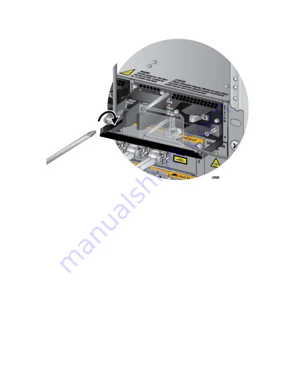
Figure 149. Connecting the Positive Lead Wire
5. Wrap the negative lead wire clockwise around the remaining terminal
screw and secure the screw and wire to the negative terminal
connection on the terminal block with a #3 Phillips-head screwdriver,
as shown in Figure 150 on page 225. The negative terminal is on the
right.
Содержание AT-SB*81CFC960
Страница 20: ...20...
Страница 34: ...Chapter 1 Chassis and Power Supplies 34 Section I Hardware Overview...
Страница 94: ...Chapter 3 AT SBx81CFC960 Controller Fabric Card 94 Section I Hardware Overview...
Страница 96: ...96...
Страница 142: ...Chapter 6 Installing the Power Supplies 142 Section II Installing the Chassis...
Страница 166: ...Chapter 7 Installing the AT SBx81CFC960 Controller and Ethernet Line Cards 166 Section II Installing the Chassis...
Страница 230: ...Chapter 10 Powering On the Chassis 230 Section II Installing the Chassis...
Страница 254: ...Chapter 12 Troubleshooting 254 Section II Installing the Chassis...
Страница 298: ...Chapter 14 Upgrading the Controller Fabric Card 298 Section II Installing the Chassis...
Страница 300: ...300...
Страница 314: ...Chapter 15 VCStack Plus Overview 314 Section III Building a Stack with VCStack Plus...
Страница 356: ...Appendix A Technical Specifications 356...


