


Getting Started
1
Agilent InfiniiVision 2000 X-Series Oscilloscopes User's Guide
31
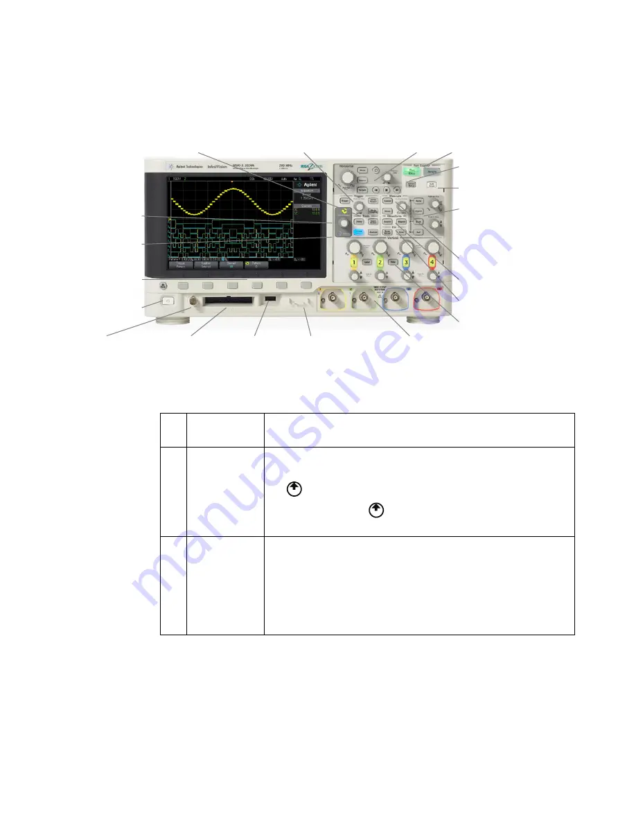
5. Tools keys
1. Power switch
2. Softkeys
3. [Intensity] key
4. Entry knob
6. Trigger controls
13. Waveform keys
18. Demo 2, Ground,
and Demo 1
terminals
17. Analog
channel
inputs
19. USB
Host
port
15. [Help] key
14. File keys
8. Run Control keys
12. Measure controls
11. Additional
waveform
controls
7. Horizontal controls
10. [Auto Scale] key
9. [Default Setup] key
16 Vertical controls
21. Waveform
generator
output
20. Digital
channel
inputs
1.
Power switch
Press once to switch power on; press again to switch power off. See
“Power-On the Oscilloscope"
on page 25.
2.
Softkeys
The functions of these keys change based upon the menus shown on the
display directly above the keys.
The
Back/Up key moves up in the softkey menu hierarchy. At the
top of the hierarchy, the
Back/Up key turns the menus off, and
oscilloscope information is shown instead.
3.
[Intensity] key
Press the key to illuminate it. When illuminated, turn the Entry knob to
adjust waveform intensity.
You can vary the intensity control to bring out signal detail, much like an
analog oscilloscope.
Digital channel waveform intensity is not adjustable.
More details about using the Intensity control to view signal detail are on
“To adjust waveform intensity"
on page 111.
Back
Back
Содержание 2000 X-Series
Страница 1: ...s1 Agilent InfiniiVision 2000 X Series Oscilloscopes User s Guide ...
Страница 20: ...20 Agilent InfiniiVision 2000 X Series Oscilloscopes User s Guide ...
Страница 44: ...44 Agilent InfiniiVision 2000 X Series Oscilloscopes User s Guide 1 Getting Started ...
Страница 58: ...58 Agilent InfiniiVision 2000 X Series Oscilloscopes User s Guide 2 Horizontal Controls ...
Страница 66: ...66 Agilent InfiniiVision 2000 X Series Oscilloscopes User s Guide 3 Vertical Controls ...
Страница 80: ...80 Agilent InfiniiVision 2000 X Series Oscilloscopes User s Guide 4 Math Waveforms ...
Страница 104: ...104 Agilent InfiniiVision 2000 X Series Oscilloscopes User s Guide 6 Digital Channels ...
Страница 110: ...110 Agilent InfiniiVision 2000 X Series Oscilloscopes User s Guide 7 Serial Decode ...
Страница 116: ...116 Agilent InfiniiVision 2000 X Series Oscilloscopes User s Guide 8 Display Settings ...
Страница 152: ...152 Agilent InfiniiVision 2000 X Series Oscilloscopes User s Guide 11 Trigger Mode Coupling ...
Страница 178: ...178 Agilent InfiniiVision 2000 X Series Oscilloscopes User s Guide 13 Cursors ...
Страница 214: ...214 Agilent InfiniiVision 2000 X Series Oscilloscopes User s Guide 16 Digital Voltmeter ...
Страница 226: ...226 Agilent InfiniiVision 2000 X Series Oscilloscopes User s Guide 17 Waveform Generator ...
Страница 238: ...238 Agilent InfiniiVision 2000 X Series Oscilloscopes User s Guide 18 Save Recall Setups Screens Data ...
Страница 244: ...244 Agilent InfiniiVision 2000 X Series Oscilloscopes User s Guide 19 Print Screens ...
Страница 280: ...280 Agilent InfiniiVision 2000 X Series Oscilloscopes User s Guide 21 Web Interface ...
Страница 334: ...334 Agilent InfiniiVision 2000 X Series Oscilloscopes User s Guide 24 I2C SPI Triggering and Serial Decode ...
Страница 352: ...352 Agilent InfiniiVision 2000 X Series Oscilloscopes User s Guide Index ...


