WA1 not grounded
WA2 not grounded
WA1 and WA2 interconn
WA1 not grounded
WA2 not grounded
WA1 and WA2 interconn
. . .
. .
Station bus
189
WA1
WA2
Bay 1
Bay n
Bus coupler
WA1 ungrounded
WA1 ungrounded
WA1 and WA2 interconn
WA1 and WA2 interconn
in other bay
289
989
189
289
989
289
189
189G
289G
en05000494_ansi.vsd
Disc 189 and 289 closed
Disc 189 and 289 closed
152
152
152
ANSI05000494 V1 EN
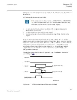
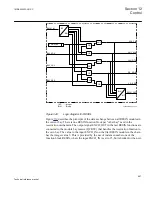
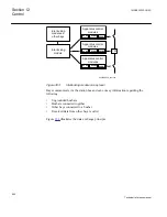
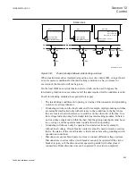
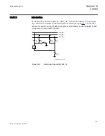
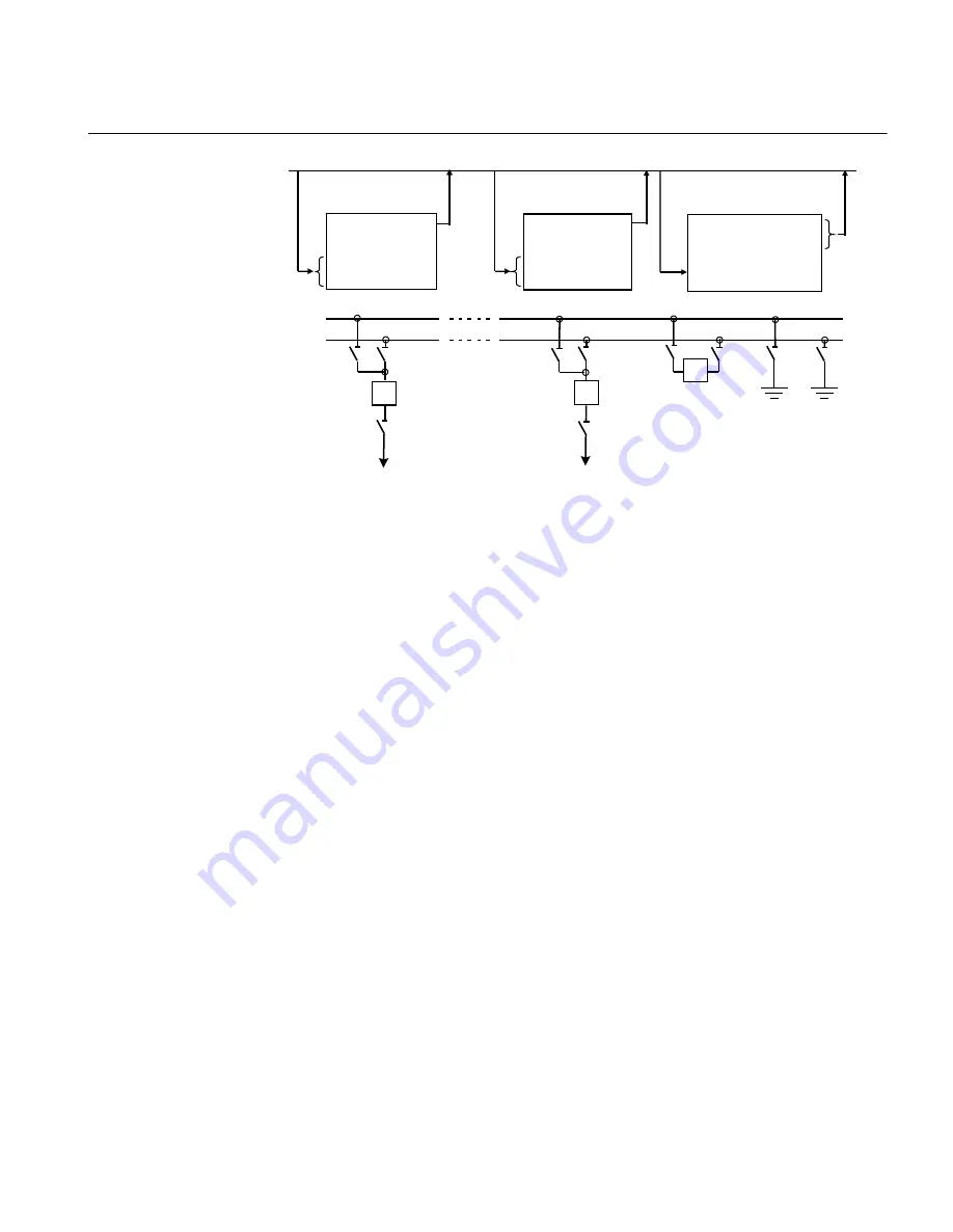
Figure 354:
Data exchange between interlocking modules
When invalid data such as intermediate position, loss of a control IED, or input board
error are used as conditions for the interlocking condition in a bay, a release for
execution of the function will not be given.
On the local HMI an override function exists, which can be used to bypass the
interlocking function in cases where not all the data required for the condition is valid.
For all interlocking modules these general rules apply:
•
The interlocking conditions for opening or closing of disconnectors and grounding
switches are always identical.
•
Grounding switches on the line feeder end, for example, rapid grounding switches,
are normally interlocked only with reference to the conditions in the bay where
they are located, not with reference to switches on the other side of the line. So a
line voltage indication may be included into line interlocking modules. If there is
no line voltage supervision within the bay, then the appropriate inputs must be set
to
no voltage
, and the operator must consider this when operating.
•
Grounding switches can only be operated on isolated sections for example,
without load/voltage. Circuit breaker contacts cannot be used to isolate a section,
that is, the status of the circuit breaker is irrelevant as far as the grounding switch
operation is concerned.
•
Disconnectors cannot break power current or connect different voltage systems.
Disconnectors in series with a circuit breaker can only be operated if the circuit
breaker is open, or if the disconnectors operate in parallel with other closed
connections. Other disconnectors can be operated if one side is completely
1MRK505222-UUS C
Section 12
Control
693
Technical reference manual
Содержание Relion 670 series
Страница 1: ...Relion 670 series Line differential protection RED670 ANSI Technical reference manual...
Страница 2: ......
Страница 40: ...34...
Страница 50: ...44...
Страница 60: ...54...
Страница 126: ...120...
Страница 384: ...378...
Страница 496: ...490...
Страница 556: ...550...
Страница 602: ...596...
Страница 620: ...614...
Страница 794: ...788...
Страница 864: ...858...
Страница 988: ...982...
Страница 998: ...992...
Страница 1084: ...1078...
Страница 1164: ...1158...
Страница 1168: ...1162...
Страница 1170: ...1MRK002802 AB 1 670 1 2 PG ANSI V1 EN Section 21 1MRK505222 UUS C Connection diagrams 1164 Technical reference manual...
Страница 1171: ...1MRK002802 AB 2 670 1 2 PG ANSI V1 EN 1MRK505222 UUS C Section 21 Connection diagrams 1165 Technical reference manual...
Страница 1172: ...1MRK002802 AB 3 670 1 2 PG ANSI V1 EN Section 21 1MRK505222 UUS C Connection diagrams 1166 Technical reference manual...
Страница 1173: ...1MRK002802 AB 4 670 1 2 PG ANSI V1 EN 1MRK505222 UUS C Section 21 Connection diagrams 1167 Technical reference manual...
Страница 1174: ...1MRK002802 AB 5 670 1 2 ANSI V1 EN Section 21 1MRK505222 UUS C Connection diagrams 1168 Technical reference manual...
Страница 1175: ...1MRK002802 AB 6 670 1 2 ANSI V1 EN 1MRK505222 UUS C Section 21 Connection diagrams 1169 Technical reference manual...
Страница 1176: ...1MRK002802 AB 7 670 1 2 ANSI V1 EN Section 21 1MRK505222 UUS C Connection diagrams 1170 Technical reference manual...
Страница 1177: ...1MRK002802 AB 8 670 1 2 ANSI V1 EN 1MRK505222 UUS C Section 21 Connection diagrams 1171 Technical reference manual...
Страница 1178: ...1MRK002802 AB 9 670 1 2 ANSI V1 EN Section 21 1MRK505222 UUS C Connection diagrams 1172 Technical reference manual...
Страница 1179: ...1MRK002802 AB 10 670 1 2 ANSI V1 EN 1MRK505222 UUS C Section 21 Connection diagrams 1173 Technical reference manual...
Страница 1180: ...1MRK002802 AB 11 670 1 2 ANSI V1 EN Section 21 1MRK505222 UUS C Connection diagrams 1174 Technical reference manual...
Страница 1181: ...1MRK002802 AB 12 670 1 2 ANSI V1 EN 1MRK505222 UUS C Section 21 Connection diagrams 1175 Technical reference manual...
Страница 1182: ...1MRK002802 AB 13 670 1 2 ANSI V1 EN Section 21 1MRK505222 UUS C Connection diagrams 1176 Technical reference manual...
Страница 1183: ...1MRK002802 AB 14 670 1 2 ANSI V1 EN 1MRK505222 UUS C Section 21 Connection diagrams 1177 Technical reference manual...
Страница 1184: ...1MRK002802 AB 15 670 1 2 ANSI V1 EN Section 21 1MRK505222 UUS C Connection diagrams 1178 Technical reference manual...
Страница 1220: ...1214...
Страница 1230: ...1224...
Страница 1231: ...1225...

