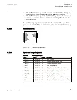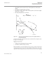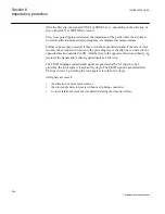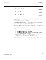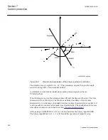
based on the selected phase preference. A number of different phase preference
combinations are available for selection.
6.15.2
Principle of operation
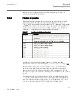
Phase preference logic PPLPHIZ has 10 operation modes, which can be set by the
parameter
OperMode
. The different modes and their explanation are shown in
table
below. The difference between cyclic and acyclic operation can be explained
by the following example. Assume a A fault on one line and a C fault on another line.
For
OperMode
=
1231c
the line with C fault will be tripped (C before A) while for
OperMode
=
123a
the line with A 1 fault will be tripped (A before C).
Table 179:
Operation modes for Phase preference logic
OperMode
Description
No filter
No filter, phase-to-phase measuring loops are not blocked during single phase-to-
ground faults. Tripping is allowed without any particular phase preference at cross-
country faults
No pref
No preference, trip is blocked during single phase-to-ground faults, trip is
allowed without any particular phase preference at cross-country fault
1231 c
Cyclic 1231c; A before B before C before C
1321 c
Cyclic 1321c; A before C before B before A
123 a
Acyclic 123a; A before B beforeC
132 a
Acyclic 132a;A before C beforeB
213 a
Acyclic 213a; B before A before C
231 a
Acyclic 231a; B before C beforeA
312 a
Acyclic 312a; C before B beforeA
321 a
Acyclic 321a; C before B before A
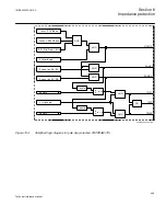
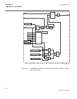
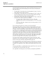
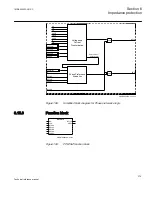
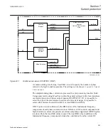
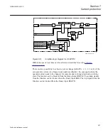
The function can be divided into two parts; one labeled voltage and current
discrimination and the second one labeled phase preference evaluation, see figure
The aim with the voltage and current discrimination part is to discriminate faulty
phases and to determine if there is a cross-country fault. If cross-country fault is
detected, an internal signal “Detected cross-country fault” is created and sent to the
phase preference part to be used in the evaluation process for determining the condition
for trip.
The voltage and current discrimination part gives phase segregated pickup signals if
the respective measured phase voltage is below the setting parameter
PU27PN
at the
same time as the zero sequence voltage is above the setting parameter
3V0Pickup
. If
there is a pickup in any phase the PICKUP output signal will be activated.
1MRK505222-UUS C
Section 6
Impedance protection
373
Technical reference manual
Содержание Relion 670 series
Страница 1: ...Relion 670 series Line differential protection RED670 ANSI Technical reference manual...
Страница 2: ......
Страница 40: ...34...
Страница 50: ...44...
Страница 60: ...54...
Страница 126: ...120...
Страница 384: ...378...
Страница 496: ...490...
Страница 556: ...550...
Страница 602: ...596...
Страница 620: ...614...
Страница 794: ...788...
Страница 864: ...858...
Страница 988: ...982...
Страница 998: ...992...
Страница 1084: ...1078...
Страница 1164: ...1158...
Страница 1168: ...1162...
Страница 1170: ...1MRK002802 AB 1 670 1 2 PG ANSI V1 EN Section 21 1MRK505222 UUS C Connection diagrams 1164 Technical reference manual...
Страница 1171: ...1MRK002802 AB 2 670 1 2 PG ANSI V1 EN 1MRK505222 UUS C Section 21 Connection diagrams 1165 Technical reference manual...
Страница 1172: ...1MRK002802 AB 3 670 1 2 PG ANSI V1 EN Section 21 1MRK505222 UUS C Connection diagrams 1166 Technical reference manual...
Страница 1173: ...1MRK002802 AB 4 670 1 2 PG ANSI V1 EN 1MRK505222 UUS C Section 21 Connection diagrams 1167 Technical reference manual...
Страница 1174: ...1MRK002802 AB 5 670 1 2 ANSI V1 EN Section 21 1MRK505222 UUS C Connection diagrams 1168 Technical reference manual...
Страница 1175: ...1MRK002802 AB 6 670 1 2 ANSI V1 EN 1MRK505222 UUS C Section 21 Connection diagrams 1169 Technical reference manual...
Страница 1176: ...1MRK002802 AB 7 670 1 2 ANSI V1 EN Section 21 1MRK505222 UUS C Connection diagrams 1170 Technical reference manual...
Страница 1177: ...1MRK002802 AB 8 670 1 2 ANSI V1 EN 1MRK505222 UUS C Section 21 Connection diagrams 1171 Technical reference manual...
Страница 1178: ...1MRK002802 AB 9 670 1 2 ANSI V1 EN Section 21 1MRK505222 UUS C Connection diagrams 1172 Technical reference manual...
Страница 1179: ...1MRK002802 AB 10 670 1 2 ANSI V1 EN 1MRK505222 UUS C Section 21 Connection diagrams 1173 Technical reference manual...
Страница 1180: ...1MRK002802 AB 11 670 1 2 ANSI V1 EN Section 21 1MRK505222 UUS C Connection diagrams 1174 Technical reference manual...
Страница 1181: ...1MRK002802 AB 12 670 1 2 ANSI V1 EN 1MRK505222 UUS C Section 21 Connection diagrams 1175 Technical reference manual...
Страница 1182: ...1MRK002802 AB 13 670 1 2 ANSI V1 EN Section 21 1MRK505222 UUS C Connection diagrams 1176 Technical reference manual...
Страница 1183: ...1MRK002802 AB 14 670 1 2 ANSI V1 EN 1MRK505222 UUS C Section 21 Connection diagrams 1177 Technical reference manual...
Страница 1184: ...1MRK002802 AB 15 670 1 2 ANSI V1 EN Section 21 1MRK505222 UUS C Connection diagrams 1178 Technical reference manual...
Страница 1220: ...1214...
Страница 1230: ...1224...
Страница 1231: ...1225...

