•
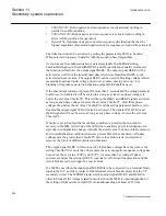
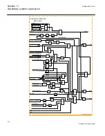
The input BLOCK is activated
•
The input BLKTRIP is activated at the same time as the internal signal
fufailStarted is not present
•
The operation mode selector
OpModeSel
is set to
Disable
.
•
The IED is in TEST status (TEST-ACTIVE is high) and the function has been
blocked from the HMI (
BlockFUSE=Yes
)
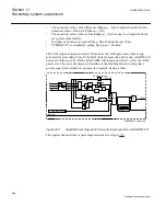
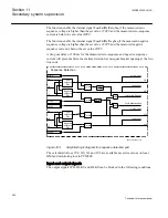
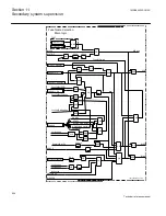
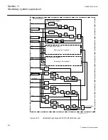
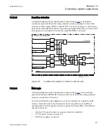
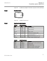
The input BLOCK signal is a general purpose blocking signal of the fuse failure
supervision function. It can be connected to a binary input of the IED in order to
receive a block command from external devices or can be software connected to other
internal functions of the IED itself in order to receive a block command from internal
functions. Through OR gate it can be connected to both binary inputs and internal
function outputs.
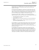
The input BLKSP is intended to be connected to the trip output at any of the protection
functions included in the IED. When activated for more than 20 ms, the operation of
the fuse failure is blocked during a fixed time of 100 ms. The aim is to increase the
security against unwanted operations during the opening of the breaker, which might
cause unbalance conditions for which the fuse failure might operate.
The output signal BLKZ will also be blocked if the internal dead line detection is
activated. The block signal has a 200 ms drop-out time delay.
The input signal MCBOP is supposed to be connected via a terminal binary input to the
N.C. auxiliary contact of the miniature circuit breaker protecting the VT secondary
circuit. The MCBOP signal sets the output signals BLKU and BLKZ in order to block
all the voltage related functions when the MCB is open independent of the setting of
OpModeSel
selector. The additional drop-out timer of 150 ms prolongs the presence of
MCBOP signal to prevent the unwanted operation of voltage dependent function due to
non simultaneous closing of the main contacts of the miniature circuit breaker.
The input signal 89b is supposed to be connected via a terminal binary input to the
N.C. auxiliary contact of the line disconnector. The 89b signal sets the output signal
BLKU in order to block the voltage related functions when the line disconnector is
open. The impedance protection function is not affected by the position of the line
disconnector since there will be no line currents that can cause malfunction of the
distance protection. If DISCPOS=0 it signifies that the line is connected to the system
and when the DISCPOS=1 it signifies that the line is disconnected from the system and
the block signal BLKU is generated.
The output BLKU can be used for blocking the voltage related measuring functions
(undervoltage protection, synchro-check and so on) except for the impedance protection.
The function output BLKZ shall be used for blocking the impedance protection function.
1MRK505222-UUS C
Section 11
Secondary system supervision
603
Technical reference manual
Содержание Relion 670 series
Страница 1: ...Relion 670 series Line differential protection RED670 ANSI Technical reference manual...
Страница 2: ......
Страница 40: ...34...
Страница 50: ...44...
Страница 60: ...54...
Страница 126: ...120...
Страница 384: ...378...
Страница 496: ...490...
Страница 556: ...550...
Страница 602: ...596...
Страница 620: ...614...
Страница 794: ...788...
Страница 864: ...858...
Страница 988: ...982...
Страница 998: ...992...
Страница 1084: ...1078...
Страница 1164: ...1158...
Страница 1168: ...1162...
Страница 1170: ...1MRK002802 AB 1 670 1 2 PG ANSI V1 EN Section 21 1MRK505222 UUS C Connection diagrams 1164 Technical reference manual...
Страница 1171: ...1MRK002802 AB 2 670 1 2 PG ANSI V1 EN 1MRK505222 UUS C Section 21 Connection diagrams 1165 Technical reference manual...
Страница 1172: ...1MRK002802 AB 3 670 1 2 PG ANSI V1 EN Section 21 1MRK505222 UUS C Connection diagrams 1166 Technical reference manual...
Страница 1173: ...1MRK002802 AB 4 670 1 2 PG ANSI V1 EN 1MRK505222 UUS C Section 21 Connection diagrams 1167 Technical reference manual...
Страница 1174: ...1MRK002802 AB 5 670 1 2 ANSI V1 EN Section 21 1MRK505222 UUS C Connection diagrams 1168 Technical reference manual...
Страница 1175: ...1MRK002802 AB 6 670 1 2 ANSI V1 EN 1MRK505222 UUS C Section 21 Connection diagrams 1169 Technical reference manual...
Страница 1176: ...1MRK002802 AB 7 670 1 2 ANSI V1 EN Section 21 1MRK505222 UUS C Connection diagrams 1170 Technical reference manual...
Страница 1177: ...1MRK002802 AB 8 670 1 2 ANSI V1 EN 1MRK505222 UUS C Section 21 Connection diagrams 1171 Technical reference manual...
Страница 1178: ...1MRK002802 AB 9 670 1 2 ANSI V1 EN Section 21 1MRK505222 UUS C Connection diagrams 1172 Technical reference manual...
Страница 1179: ...1MRK002802 AB 10 670 1 2 ANSI V1 EN 1MRK505222 UUS C Section 21 Connection diagrams 1173 Technical reference manual...
Страница 1180: ...1MRK002802 AB 11 670 1 2 ANSI V1 EN Section 21 1MRK505222 UUS C Connection diagrams 1174 Technical reference manual...
Страница 1181: ...1MRK002802 AB 12 670 1 2 ANSI V1 EN 1MRK505222 UUS C Section 21 Connection diagrams 1175 Technical reference manual...
Страница 1182: ...1MRK002802 AB 13 670 1 2 ANSI V1 EN Section 21 1MRK505222 UUS C Connection diagrams 1176 Technical reference manual...
Страница 1183: ...1MRK002802 AB 14 670 1 2 ANSI V1 EN 1MRK505222 UUS C Section 21 Connection diagrams 1177 Technical reference manual...
Страница 1184: ...1MRK002802 AB 15 670 1 2 ANSI V1 EN Section 21 1MRK505222 UUS C Connection diagrams 1178 Technical reference manual...
Страница 1220: ...1214...
Страница 1230: ...1224...
Страница 1231: ...1225...

