


12.4.2
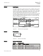
Principle of operation
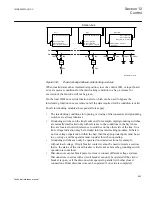
The interlocking function consists of software modules located in each control IED.
The function is distributed and not dependent on any central function. Communication
between modules in different bays is performed via the station bus.
The reservation function (see section
) is used to ensure that HV
apparatuses that might affect the interlock are blocked during the time gap, which
arises between position updates. This can be done by means of the communication
system, reserving all HV apparatuses that might influence the interlocking condition of
the intended operation. The reservation is maintained until the operation is performed.
After the selection and reservation of an apparatus, the function has complete data on
the status of all apparatuses in the switchyard that are affected by the selection. Other
operators cannot interfere with the reserved apparatus or the status of switching devices
that may affect it.
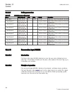
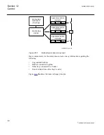
The open or closed positions of the HV apparatuses are inputs to software modules
distributed in the control IEDs. Each module contains the interlocking logic for a bay.
The interlocking logic in a module is different, depending on the bay function and the
switchyard arrangements, that is, double-breaker or breaker-and-a-half bays have
different modules. Specific interlocking conditions and connections between standard
interlocking modules are performed with an engineering tool. Bay-level interlocking
signals can include the following kind of information:
•
Positions of HV apparatuses (sometimes per phase)
•
Valid positions (if evaluated in the control module)
•
External release (to add special conditions for release)
•
Line voltage (to block operation of line grounding switch)
•
Output signals to release the HV apparatus
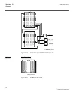
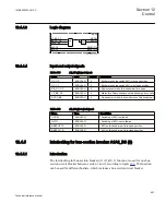
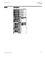
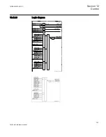
The interlocking module is connected to the surrounding functions within a bay as
shown in figure
1MRK505222-UUS C
Section 12
Control
691
Technical reference manual
Содержание Relion 670 series
Страница 1: ...Relion 670 series Line differential protection RED670 ANSI Technical reference manual...
Страница 2: ......
Страница 40: ...34...
Страница 50: ...44...
Страница 60: ...54...
Страница 126: ...120...
Страница 384: ...378...
Страница 496: ...490...
Страница 556: ...550...
Страница 602: ...596...
Страница 620: ...614...
Страница 794: ...788...
Страница 864: ...858...
Страница 988: ...982...
Страница 998: ...992...
Страница 1084: ...1078...
Страница 1164: ...1158...
Страница 1168: ...1162...
Страница 1170: ...1MRK002802 AB 1 670 1 2 PG ANSI V1 EN Section 21 1MRK505222 UUS C Connection diagrams 1164 Technical reference manual...
Страница 1171: ...1MRK002802 AB 2 670 1 2 PG ANSI V1 EN 1MRK505222 UUS C Section 21 Connection diagrams 1165 Technical reference manual...
Страница 1172: ...1MRK002802 AB 3 670 1 2 PG ANSI V1 EN Section 21 1MRK505222 UUS C Connection diagrams 1166 Technical reference manual...
Страница 1173: ...1MRK002802 AB 4 670 1 2 PG ANSI V1 EN 1MRK505222 UUS C Section 21 Connection diagrams 1167 Technical reference manual...
Страница 1174: ...1MRK002802 AB 5 670 1 2 ANSI V1 EN Section 21 1MRK505222 UUS C Connection diagrams 1168 Technical reference manual...
Страница 1175: ...1MRK002802 AB 6 670 1 2 ANSI V1 EN 1MRK505222 UUS C Section 21 Connection diagrams 1169 Technical reference manual...
Страница 1176: ...1MRK002802 AB 7 670 1 2 ANSI V1 EN Section 21 1MRK505222 UUS C Connection diagrams 1170 Technical reference manual...
Страница 1177: ...1MRK002802 AB 8 670 1 2 ANSI V1 EN 1MRK505222 UUS C Section 21 Connection diagrams 1171 Technical reference manual...
Страница 1178: ...1MRK002802 AB 9 670 1 2 ANSI V1 EN Section 21 1MRK505222 UUS C Connection diagrams 1172 Technical reference manual...
Страница 1179: ...1MRK002802 AB 10 670 1 2 ANSI V1 EN 1MRK505222 UUS C Section 21 Connection diagrams 1173 Technical reference manual...
Страница 1180: ...1MRK002802 AB 11 670 1 2 ANSI V1 EN Section 21 1MRK505222 UUS C Connection diagrams 1174 Technical reference manual...
Страница 1181: ...1MRK002802 AB 12 670 1 2 ANSI V1 EN 1MRK505222 UUS C Section 21 Connection diagrams 1175 Technical reference manual...
Страница 1182: ...1MRK002802 AB 13 670 1 2 ANSI V1 EN Section 21 1MRK505222 UUS C Connection diagrams 1176 Technical reference manual...
Страница 1183: ...1MRK002802 AB 14 670 1 2 ANSI V1 EN 1MRK505222 UUS C Section 21 Connection diagrams 1177 Technical reference manual...
Страница 1184: ...1MRK002802 AB 15 670 1 2 ANSI V1 EN Section 21 1MRK505222 UUS C Connection diagrams 1178 Technical reference manual...
Страница 1220: ...1214...
Страница 1230: ...1224...
Страница 1231: ...1225...