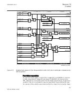
neutral (or the opposite), this need to be compensated. This is done with a setting,
which scales up the line voltage to a level equal to the bus voltage.
When the function is set to
OperationSC
=
Enabled
, the measuring will start.
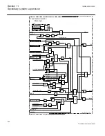
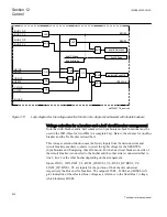
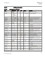
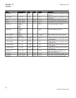
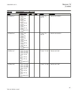
The function will compare the bus and line voltage values with the set values for
VHighBusSC
and
VHighLineSC
.
If both sides are higher than the set values, the measured values are compared with the
set values for acceptable frequency, phase angle and voltage difference:
FreqDiffA
,
FreqDiffM
,
PhaseDiffA
,
PhaseDiffM
and
VDiffSC
. If a compensation factor is set due
to the use of different voltages on the bus and line, the factor is deducted from the line
voltage before the comparison of the phase angle values.
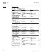
The frequency on both sides of the circuit breaker is also measured. The frequencies
must not deviate from the rated frequency more than +/-5Hz. The frequency difference
between the bus frequency and the line frequency is measured and may not exceed the
set value.
Two sets of settings for frequency difference and phase angle difference are available
and used for the manual closing and autoreclose functions respectively, as required.
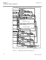
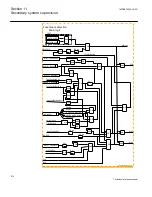
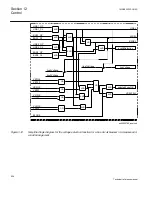
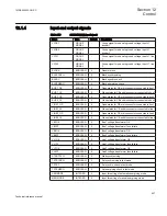
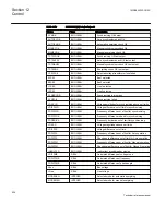
The inputs BLOCK and BLKSC are available for total block of the complete
SESRSYN (25) function and block of the Synchronism check function respectively.
Input TSTSC will allow testing of the function where the fulfilled conditions are
connected to a separate test output.
The outputs MANSYOK and AUTOSYOK are activated when the actual measured
conditions match the set conditions for the respective output. The output signal can be
delayed independently for MANSYOK and AUTOSYOK conditions.
A number of outputs are available as information about fulfilled checking conditions.
VOKSC shows that the voltages are high, VDIFFSC, FRDIFFA, FRDIFFM,
PHDIFFA, PHDIFFM shows when the voltage difference, frequency difference and
phase angle difference conditions are out of limits.
Output INADVCLS, inadvertent circuit breaker closing, indicate that the circuit
breaker has been closed by some other equipment or function than SESRSYN. The
output is activated, if the voltage condition is fulfilled at the same time the phase angle
difference between bus and line is suddenly changed from being larger than 60 degrees
to smaller than 5 degrees.
1MRK505222-UUS C
Section 12
Control
617
Technical reference manual
Содержание Relion 670 series
Страница 1: ...Relion 670 series Line differential protection RED670 ANSI Technical reference manual...
Страница 2: ......
Страница 40: ...34...
Страница 50: ...44...
Страница 60: ...54...
Страница 126: ...120...
Страница 384: ...378...
Страница 496: ...490...
Страница 556: ...550...
Страница 602: ...596...
Страница 620: ...614...
Страница 794: ...788...
Страница 864: ...858...
Страница 988: ...982...
Страница 998: ...992...
Страница 1084: ...1078...
Страница 1164: ...1158...
Страница 1168: ...1162...
Страница 1170: ...1MRK002802 AB 1 670 1 2 PG ANSI V1 EN Section 21 1MRK505222 UUS C Connection diagrams 1164 Technical reference manual...
Страница 1171: ...1MRK002802 AB 2 670 1 2 PG ANSI V1 EN 1MRK505222 UUS C Section 21 Connection diagrams 1165 Technical reference manual...
Страница 1172: ...1MRK002802 AB 3 670 1 2 PG ANSI V1 EN Section 21 1MRK505222 UUS C Connection diagrams 1166 Technical reference manual...
Страница 1173: ...1MRK002802 AB 4 670 1 2 PG ANSI V1 EN 1MRK505222 UUS C Section 21 Connection diagrams 1167 Technical reference manual...
Страница 1174: ...1MRK002802 AB 5 670 1 2 ANSI V1 EN Section 21 1MRK505222 UUS C Connection diagrams 1168 Technical reference manual...
Страница 1175: ...1MRK002802 AB 6 670 1 2 ANSI V1 EN 1MRK505222 UUS C Section 21 Connection diagrams 1169 Technical reference manual...
Страница 1176: ...1MRK002802 AB 7 670 1 2 ANSI V1 EN Section 21 1MRK505222 UUS C Connection diagrams 1170 Technical reference manual...
Страница 1177: ...1MRK002802 AB 8 670 1 2 ANSI V1 EN 1MRK505222 UUS C Section 21 Connection diagrams 1171 Technical reference manual...
Страница 1178: ...1MRK002802 AB 9 670 1 2 ANSI V1 EN Section 21 1MRK505222 UUS C Connection diagrams 1172 Technical reference manual...
Страница 1179: ...1MRK002802 AB 10 670 1 2 ANSI V1 EN 1MRK505222 UUS C Section 21 Connection diagrams 1173 Technical reference manual...
Страница 1180: ...1MRK002802 AB 11 670 1 2 ANSI V1 EN Section 21 1MRK505222 UUS C Connection diagrams 1174 Technical reference manual...
Страница 1181: ...1MRK002802 AB 12 670 1 2 ANSI V1 EN 1MRK505222 UUS C Section 21 Connection diagrams 1175 Technical reference manual...
Страница 1182: ...1MRK002802 AB 13 670 1 2 ANSI V1 EN Section 21 1MRK505222 UUS C Connection diagrams 1176 Technical reference manual...
Страница 1183: ...1MRK002802 AB 14 670 1 2 ANSI V1 EN 1MRK505222 UUS C Section 21 Connection diagrams 1177 Technical reference manual...
Страница 1184: ...1MRK002802 AB 15 670 1 2 ANSI V1 EN Section 21 1MRK505222 UUS C Connection diagrams 1178 Technical reference manual...
Страница 1220: ...1214...
Страница 1230: ...1224...
Страница 1231: ...1225...

