


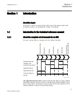
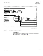


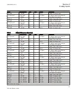

Signal names
Input and output logic signals consist of two groups of letters separated by two dashes.
The first group consists of up to four letters and presents the abbreviated name for the
corresponding function. The second group presents the functionality of the particular
signal. According to this explanation, the meaning of the signal BLKTR in figure
as follows:
•
BLKTR informs the user that the signal will BLOCK the TRIP command from the
under-voltage function, when its value is a logical one (1).
Input signals are always on the left hand side, and output signals on the right hand side.
Settings are not displayed.
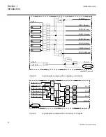
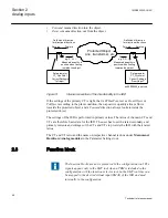
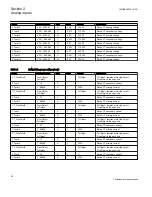
Input and output signals
In a logic diagram, input and output signal paths are shown as a lines that touch the
outer border of the diagram.
Input and output signals can be configured using the ACT tool. They can be connected
to the inputs and outputs of other functions and to binary inputs and outputs. Examples
of input signals are BLKTR, BLOCK and VTSU. Examples output signals are TRIP,
START, STL1, STL2, STL3.
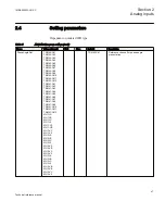
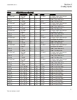
Setting parameters
Signals in frames with a shaded area on their right hand side represent setting
parameter signals. These parameters can only be set via the PST or LHMI. Their values
are high (1) only when the corresponding setting parameter is set to the symbolic value
specified within the frame. Example is the signal Block TUV=Yes. Their logical
values correspond automatically to the selected setting value.
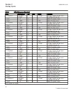
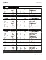
Internal signals
Internal signals are illustrated graphically and end approximately 2 mm from the frame
edge. If an internal signal path cannot be drawn with a continuous line, the suffix -int is
added to the signal name to indicate where the signal starts and continues, see figure
.
Section 1
1MRK505222-UUS C
Introduction
38
Technical reference manual
Содержание Relion 670 series
Страница 1: ...Relion 670 series Line differential protection RED670 ANSI Technical reference manual...
Страница 2: ......
Страница 40: ...34...
Страница 50: ...44...
Страница 60: ...54...
Страница 126: ...120...
Страница 384: ...378...
Страница 496: ...490...
Страница 556: ...550...
Страница 602: ...596...
Страница 620: ...614...
Страница 794: ...788...
Страница 864: ...858...
Страница 988: ...982...
Страница 998: ...992...
Страница 1084: ...1078...
Страница 1164: ...1158...
Страница 1168: ...1162...
Страница 1170: ...1MRK002802 AB 1 670 1 2 PG ANSI V1 EN Section 21 1MRK505222 UUS C Connection diagrams 1164 Technical reference manual...
Страница 1171: ...1MRK002802 AB 2 670 1 2 PG ANSI V1 EN 1MRK505222 UUS C Section 21 Connection diagrams 1165 Technical reference manual...
Страница 1172: ...1MRK002802 AB 3 670 1 2 PG ANSI V1 EN Section 21 1MRK505222 UUS C Connection diagrams 1166 Technical reference manual...
Страница 1173: ...1MRK002802 AB 4 670 1 2 PG ANSI V1 EN 1MRK505222 UUS C Section 21 Connection diagrams 1167 Technical reference manual...
Страница 1174: ...1MRK002802 AB 5 670 1 2 ANSI V1 EN Section 21 1MRK505222 UUS C Connection diagrams 1168 Technical reference manual...
Страница 1175: ...1MRK002802 AB 6 670 1 2 ANSI V1 EN 1MRK505222 UUS C Section 21 Connection diagrams 1169 Technical reference manual...
Страница 1176: ...1MRK002802 AB 7 670 1 2 ANSI V1 EN Section 21 1MRK505222 UUS C Connection diagrams 1170 Technical reference manual...
Страница 1177: ...1MRK002802 AB 8 670 1 2 ANSI V1 EN 1MRK505222 UUS C Section 21 Connection diagrams 1171 Technical reference manual...
Страница 1178: ...1MRK002802 AB 9 670 1 2 ANSI V1 EN Section 21 1MRK505222 UUS C Connection diagrams 1172 Technical reference manual...
Страница 1179: ...1MRK002802 AB 10 670 1 2 ANSI V1 EN 1MRK505222 UUS C Section 21 Connection diagrams 1173 Technical reference manual...
Страница 1180: ...1MRK002802 AB 11 670 1 2 ANSI V1 EN Section 21 1MRK505222 UUS C Connection diagrams 1174 Technical reference manual...
Страница 1181: ...1MRK002802 AB 12 670 1 2 ANSI V1 EN 1MRK505222 UUS C Section 21 Connection diagrams 1175 Technical reference manual...
Страница 1182: ...1MRK002802 AB 13 670 1 2 ANSI V1 EN Section 21 1MRK505222 UUS C Connection diagrams 1176 Technical reference manual...
Страница 1183: ...1MRK002802 AB 14 670 1 2 ANSI V1 EN 1MRK505222 UUS C Section 21 Connection diagrams 1177 Technical reference manual...
Страница 1184: ...1MRK002802 AB 15 670 1 2 ANSI V1 EN Section 21 1MRK505222 UUS C Connection diagrams 1178 Technical reference manual...
Страница 1220: ...1214...
Страница 1230: ...1224...
Страница 1231: ...1225...