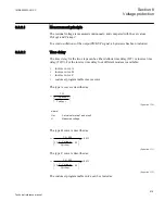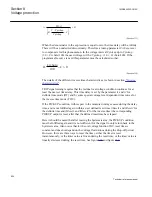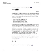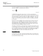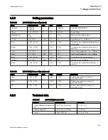
2 is unfortunately most often not true. For a two-winding power transformer the
leakage reactances of the two windings depend on how the windings are located on the
core with respect to each other. In the case of three-winding power transformers the
situation is still more complex. If a user has the knowledge on the leakage reactance,
then it should applied. If a user has no idea about it,
XLeakage
can be set to X
c/2
.
OEXPVPH (24) protection will then take the given measured voltage V, as the induced
voltage E.
It is assumed that overexcitation is a symmetrical phenomenon, caused by events such
as loss-of-load, etc. It will be observed that a high phase-to-ground voltage does not
mean overexcitation. For example, in an ungrounded power system, a single phase-to-
ground fault means high voltages of the “healthy” two phases-to-ground, but no
overexcitation on any winding. The phase-to-phase voltages will remain essentially
unchanged. The important voltage is the voltage between the two ends of each winding.
8.4.2.1
Measured voltage
If one phase-to-phase voltage is available from the side where overexcitation
protection is applied, then Overexcitation protection OEXPVPH (24) shall be set to
measure this voltage,
MeasuredV
. The particular voltage which is used determines the
two currents that must be used. This must be chosen with the setting
MeasuredI
.
It is extremely important that
MeasuredV
and
MeasuredI
are set to
same value.
If, for example, voltage Vab is fed to OEXPVPH(24), then currents Ia, and Ib must be
applied. From these two input currents, current Iab = Ia - Ib is calculated internally by
the OEXPVPH (24) algorithm. The phase-to-phase voltage must be higher than 70% of
the rated value, otherwise the protection algorithm exits without calculating the
excitation. ERROR output is set to 1, and the displayed value of relative excitation V/
Hz shows 0.000.
If three phase-to-ground voltages are available from the side where overexcitation is
connected, then OEXPVPH (24) shall be set to measure positive sequence voltage and
current. In this case the positive sequence voltage and the positive sequence current are
used by OEXPVPH (24). A check is made if the positive sequence voltage is higher
than 70% of rated phase-to-ground voltage, when below this value, OEXPVPH (24)
exits immediately, and no excitation is calculated. ERROR output is set to 1, and the
displayed value of relative excitation V/Hz shows 0.000.
The frequency value is received from the pre-processing block. The function operates
for frequencies within the range of 33-60 Hz and of 42-75 Hz for 50 Hz and 60 Hz
respectively.
Section 8
1MRK505222-UUS C
Voltage protection
532
Technical reference manual
Содержание Relion 670 series
Страница 1: ...Relion 670 series Line differential protection RED670 ANSI Technical reference manual...
Страница 2: ......
Страница 40: ...34...
Страница 50: ...44...
Страница 60: ...54...
Страница 126: ...120...
Страница 384: ...378...
Страница 496: ...490...
Страница 556: ...550...
Страница 602: ...596...
Страница 620: ...614...
Страница 794: ...788...
Страница 864: ...858...
Страница 988: ...982...
Страница 998: ...992...
Страница 1084: ...1078...
Страница 1164: ...1158...
Страница 1168: ...1162...
Страница 1170: ...1MRK002802 AB 1 670 1 2 PG ANSI V1 EN Section 21 1MRK505222 UUS C Connection diagrams 1164 Technical reference manual...
Страница 1171: ...1MRK002802 AB 2 670 1 2 PG ANSI V1 EN 1MRK505222 UUS C Section 21 Connection diagrams 1165 Technical reference manual...
Страница 1172: ...1MRK002802 AB 3 670 1 2 PG ANSI V1 EN Section 21 1MRK505222 UUS C Connection diagrams 1166 Technical reference manual...
Страница 1173: ...1MRK002802 AB 4 670 1 2 PG ANSI V1 EN 1MRK505222 UUS C Section 21 Connection diagrams 1167 Technical reference manual...
Страница 1174: ...1MRK002802 AB 5 670 1 2 ANSI V1 EN Section 21 1MRK505222 UUS C Connection diagrams 1168 Technical reference manual...
Страница 1175: ...1MRK002802 AB 6 670 1 2 ANSI V1 EN 1MRK505222 UUS C Section 21 Connection diagrams 1169 Technical reference manual...
Страница 1176: ...1MRK002802 AB 7 670 1 2 ANSI V1 EN Section 21 1MRK505222 UUS C Connection diagrams 1170 Technical reference manual...
Страница 1177: ...1MRK002802 AB 8 670 1 2 ANSI V1 EN 1MRK505222 UUS C Section 21 Connection diagrams 1171 Technical reference manual...
Страница 1178: ...1MRK002802 AB 9 670 1 2 ANSI V1 EN Section 21 1MRK505222 UUS C Connection diagrams 1172 Technical reference manual...
Страница 1179: ...1MRK002802 AB 10 670 1 2 ANSI V1 EN 1MRK505222 UUS C Section 21 Connection diagrams 1173 Technical reference manual...
Страница 1180: ...1MRK002802 AB 11 670 1 2 ANSI V1 EN Section 21 1MRK505222 UUS C Connection diagrams 1174 Technical reference manual...
Страница 1181: ...1MRK002802 AB 12 670 1 2 ANSI V1 EN 1MRK505222 UUS C Section 21 Connection diagrams 1175 Technical reference manual...
Страница 1182: ...1MRK002802 AB 13 670 1 2 ANSI V1 EN Section 21 1MRK505222 UUS C Connection diagrams 1176 Technical reference manual...
Страница 1183: ...1MRK002802 AB 14 670 1 2 ANSI V1 EN 1MRK505222 UUS C Section 21 Connection diagrams 1177 Technical reference manual...
Страница 1184: ...1MRK002802 AB 15 670 1 2 ANSI V1 EN Section 21 1MRK505222 UUS C Connection diagrams 1178 Technical reference manual...
Страница 1220: ...1214...
Страница 1230: ...1224...
Страница 1231: ...1225...


