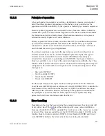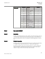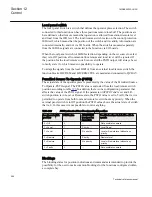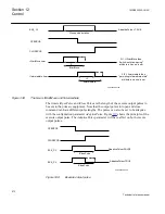
Evaluation of position
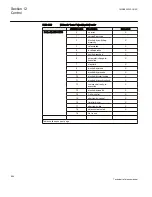
In the case when there are three one-phase switches connected to the switch control
function, the switch control will "merge" the position of the three switches to the
resulting three-phase position. In the case when the position differ between the one-
phase switches, following principles will be applied:
The position output from switch (SXCBR or SXSWI) is connected to SCSWI. With
the group signal connection the SCSWI obtains the position, time stamps and quality
attributes of the position which is used for further evaluation.
All switches in open position:
switch control position = open
All switches in close position:
switch control position = close
One switch =open, two switches= close (or
inversely):
switch control position = intermediate
Any switch in intermediate position:
switch control position = intermediate
Any switch in bad state:
switch control position = bad state
The time stamp of the output three-phase position from switch control will have the
time stamp of the last changed phase when it goes to end position. When it goes to
intermediate position or bad state, it will get the time stamp of the first changed phase.
In addition, there is also the possibility that one of the one-phase switches will change
position at any time due to a trip. Such situation is here called pole discrepancy and is
supervised by this function. In case of a pole discrepancy situation, that is, the position
of the one-phase switches are not equal for a time longer than the setting
tPoleDiscord
,
an error signal POLEDISC will be set.
In the supervision phase, the switch controller function evaluates the "cause" values
from the switch modules Circuit breaker (SXCBR)/ Circuit switch (SXSWI). At error
the "cause" value with highest priority is shown.
Blocking principles
The blocking signals are normally coming from the bay control function (QCBAY)
and via the IEC 61850 communication from the operator place.
The IEC 61850 communication has always priority over binary inputs,
e.g. a block command on binary inputs will not prevent commands over
IEC 61850.
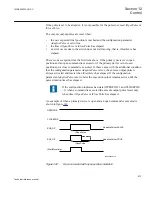
The different blocking possibilities are:
•
Block/deblock of command. It is used to block command for operation of position.
•
Blocking of function, BLOCK, signal from DO (Data Object) Behavior (IEC
61850). If DO Behavior is set to "blocked" it means that the function is active, but
1MRK505222-UUS C
Section 12
Control
663
Technical reference manual
Содержание Relion 670 series
Страница 1: ...Relion 670 series Line differential protection RED670 ANSI Technical reference manual...
Страница 2: ......
Страница 40: ...34...
Страница 50: ...44...
Страница 60: ...54...
Страница 126: ...120...
Страница 384: ...378...
Страница 496: ...490...
Страница 556: ...550...
Страница 602: ...596...
Страница 620: ...614...
Страница 794: ...788...
Страница 864: ...858...
Страница 988: ...982...
Страница 998: ...992...
Страница 1084: ...1078...
Страница 1164: ...1158...
Страница 1168: ...1162...
Страница 1170: ...1MRK002802 AB 1 670 1 2 PG ANSI V1 EN Section 21 1MRK505222 UUS C Connection diagrams 1164 Technical reference manual...
Страница 1171: ...1MRK002802 AB 2 670 1 2 PG ANSI V1 EN 1MRK505222 UUS C Section 21 Connection diagrams 1165 Technical reference manual...
Страница 1172: ...1MRK002802 AB 3 670 1 2 PG ANSI V1 EN Section 21 1MRK505222 UUS C Connection diagrams 1166 Technical reference manual...
Страница 1173: ...1MRK002802 AB 4 670 1 2 PG ANSI V1 EN 1MRK505222 UUS C Section 21 Connection diagrams 1167 Technical reference manual...
Страница 1174: ...1MRK002802 AB 5 670 1 2 ANSI V1 EN Section 21 1MRK505222 UUS C Connection diagrams 1168 Technical reference manual...
Страница 1175: ...1MRK002802 AB 6 670 1 2 ANSI V1 EN 1MRK505222 UUS C Section 21 Connection diagrams 1169 Technical reference manual...
Страница 1176: ...1MRK002802 AB 7 670 1 2 ANSI V1 EN Section 21 1MRK505222 UUS C Connection diagrams 1170 Technical reference manual...
Страница 1177: ...1MRK002802 AB 8 670 1 2 ANSI V1 EN 1MRK505222 UUS C Section 21 Connection diagrams 1171 Technical reference manual...
Страница 1178: ...1MRK002802 AB 9 670 1 2 ANSI V1 EN Section 21 1MRK505222 UUS C Connection diagrams 1172 Technical reference manual...
Страница 1179: ...1MRK002802 AB 10 670 1 2 ANSI V1 EN 1MRK505222 UUS C Section 21 Connection diagrams 1173 Technical reference manual...
Страница 1180: ...1MRK002802 AB 11 670 1 2 ANSI V1 EN Section 21 1MRK505222 UUS C Connection diagrams 1174 Technical reference manual...
Страница 1181: ...1MRK002802 AB 12 670 1 2 ANSI V1 EN 1MRK505222 UUS C Section 21 Connection diagrams 1175 Technical reference manual...
Страница 1182: ...1MRK002802 AB 13 670 1 2 ANSI V1 EN Section 21 1MRK505222 UUS C Connection diagrams 1176 Technical reference manual...
Страница 1183: ...1MRK002802 AB 14 670 1 2 ANSI V1 EN 1MRK505222 UUS C Section 21 Connection diagrams 1177 Technical reference manual...
Страница 1184: ...1MRK002802 AB 15 670 1 2 ANSI V1 EN Section 21 1MRK505222 UUS C Connection diagrams 1178 Technical reference manual...
Страница 1220: ...1214...
Страница 1230: ...1224...
Страница 1231: ...1225...

