


for slip frequencies that are larger than those for synchronism check and lower than a
set maximum level for the synchronizing function.
12.1.2
Principle of operation
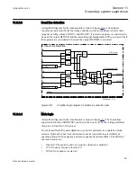
12.1.2.1
Basic functionality
The synchronism check function measures the conditions across the circuit breaker and
compares them to set limits. The output is only given when all measured quantities are
simultaneously within their set limits.
The energizing check function measures the bus and line voltages and compares them
to both high and low threshold detectors. The output is given only when the actual
measured quantities match the set conditions.
The synchronizing function measures the conditions across the circuit breaker, and also
determines the angle change occurring during the closing delay of the circuit breaker,
from the measured slip frequency. The output is given only when all measured
conditions are simultaneously within their set limits. The issue of the output is timed to
give closure at the optimal time including the time for the circuit breaker and the
closing circuit.
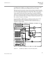
For single circuit breaker and breaker-and-a-half circuit breaker arrangements, the
SESRSYN (25) function blocks have the capability to make the necessary voltage
selection. For single circuit breaker arrangements, selection of the correct voltage is
made using auxiliary contacts of the bus disconnectors. For breaker-and-a-half circuit
breaker arrangements, correct voltage selection is made using auxiliary contacts of the
bus disconnectors as well as the circuit breakers.
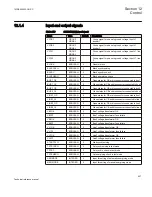
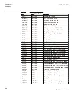
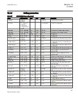
The internal logic for each function block as well as, the input and outputs, and the
setting parameters with default setting and setting ranges is described in this document.
For application related information, please refer to the application manual.
12.1.2.2
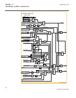
Logic diagrams
Logic diagrams
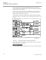
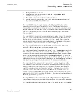
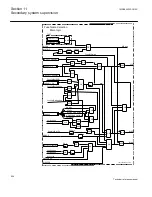
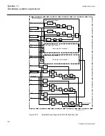
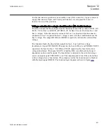
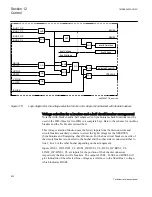
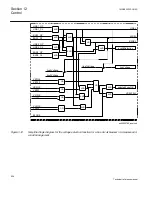
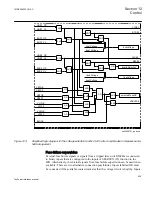
The logic diagrams that follow illustrate the main principles of the SESRSYN function
components such as Synchrocheck, Synchronizing, Energizing check and Voltage
selection, and are intended to simplify the understanding of the function.
Synchronism check
The voltage difference, frequency difference and phase angle difference values are
measured in the IED centrally and are available for the synchronism check function for
evaluation. If the bus voltage is connected as phase-phase and the line voltage as phase-
Section 12
1MRK505222-UUS C
Control
616
Technical reference manual
Содержание Relion 670 series
Страница 1: ...Relion 670 series Line differential protection RED670 ANSI Technical reference manual...
Страница 2: ......
Страница 40: ...34...
Страница 50: ...44...
Страница 60: ...54...
Страница 126: ...120...
Страница 384: ...378...
Страница 496: ...490...
Страница 556: ...550...
Страница 602: ...596...
Страница 620: ...614...
Страница 794: ...788...
Страница 864: ...858...
Страница 988: ...982...
Страница 998: ...992...
Страница 1084: ...1078...
Страница 1164: ...1158...
Страница 1168: ...1162...
Страница 1170: ...1MRK002802 AB 1 670 1 2 PG ANSI V1 EN Section 21 1MRK505222 UUS C Connection diagrams 1164 Technical reference manual...
Страница 1171: ...1MRK002802 AB 2 670 1 2 PG ANSI V1 EN 1MRK505222 UUS C Section 21 Connection diagrams 1165 Technical reference manual...
Страница 1172: ...1MRK002802 AB 3 670 1 2 PG ANSI V1 EN Section 21 1MRK505222 UUS C Connection diagrams 1166 Technical reference manual...
Страница 1173: ...1MRK002802 AB 4 670 1 2 PG ANSI V1 EN 1MRK505222 UUS C Section 21 Connection diagrams 1167 Technical reference manual...
Страница 1174: ...1MRK002802 AB 5 670 1 2 ANSI V1 EN Section 21 1MRK505222 UUS C Connection diagrams 1168 Technical reference manual...
Страница 1175: ...1MRK002802 AB 6 670 1 2 ANSI V1 EN 1MRK505222 UUS C Section 21 Connection diagrams 1169 Technical reference manual...
Страница 1176: ...1MRK002802 AB 7 670 1 2 ANSI V1 EN Section 21 1MRK505222 UUS C Connection diagrams 1170 Technical reference manual...
Страница 1177: ...1MRK002802 AB 8 670 1 2 ANSI V1 EN 1MRK505222 UUS C Section 21 Connection diagrams 1171 Technical reference manual...
Страница 1178: ...1MRK002802 AB 9 670 1 2 ANSI V1 EN Section 21 1MRK505222 UUS C Connection diagrams 1172 Technical reference manual...
Страница 1179: ...1MRK002802 AB 10 670 1 2 ANSI V1 EN 1MRK505222 UUS C Section 21 Connection diagrams 1173 Technical reference manual...
Страница 1180: ...1MRK002802 AB 11 670 1 2 ANSI V1 EN Section 21 1MRK505222 UUS C Connection diagrams 1174 Technical reference manual...
Страница 1181: ...1MRK002802 AB 12 670 1 2 ANSI V1 EN 1MRK505222 UUS C Section 21 Connection diagrams 1175 Technical reference manual...
Страница 1182: ...1MRK002802 AB 13 670 1 2 ANSI V1 EN Section 21 1MRK505222 UUS C Connection diagrams 1176 Technical reference manual...
Страница 1183: ...1MRK002802 AB 14 670 1 2 ANSI V1 EN 1MRK505222 UUS C Section 21 Connection diagrams 1177 Technical reference manual...
Страница 1184: ...1MRK002802 AB 15 670 1 2 ANSI V1 EN Section 21 1MRK505222 UUS C Connection diagrams 1178 Technical reference manual...
Страница 1220: ...1214...
Страница 1230: ...1224...
Страница 1231: ...1225...