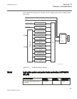

Connect the necessary signal from the autorecloser for blocking of the directional
comparison scheme, during a single-phase autoreclosing cycle, to the BLOCK input of
the directional comparison module.
13.6.2.2
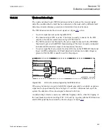
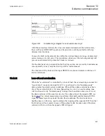
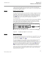
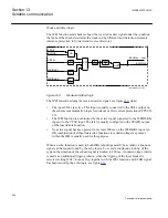
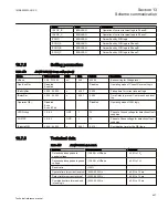
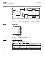
Fault current reversal logic
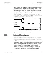
The fault current reversal logic uses a reverse directed element, connected to the input
signal IREV, which recognizes that the fault is in reverse direction. When the reverse
direction element is activated the output signal IRVL is activated which is shown in
Figure
. The logic is now ready to handle a current reversal without tripping. The
output signal IRVL will be connected to the block input on the permissive
overreaching scheme.
When the fault current is reversed on the healthy line, IRV is deactivated and IRVBLK
is activated. The
tDelayRev
timer delays the reset of the output signal. The signal
blocks operation of the overreach permissive scheme for residual current and thus
prevents unwanted operation caused by fault current reversal.
tPickUp
Rev
AND
tDelay
Rev
BLOCK
IREV
IFWD
IRVL
tPickUp
Rev
Drawing2.vsd
0
0
10ms
0
0
ANSI09000031 V1 EN
Figure 405:
Simplified logic diagram for current reversal
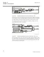
13.6.2.3
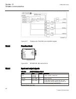
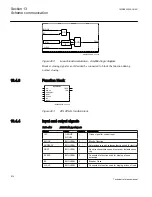
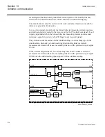
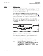
Weak-end infeed logic
The weak-end infeed function can be set to send only an echo signal (
WEI=Echo
) or an
echo signal and a trip signal (
WEI=Echo & Trip
). The corresponding logic diagrams
are depicted in Figure
The weak-end infeed logic uses normally a reverse and a forward direction element,
connected to WEIBLK2 via an OR-gate. If neither the forward nor the reverse
directional measuring element is activated during the last 200 ms, the weak-end infeed
logic echoes back the received permissive signal as shown in Figure
and Figure
. The weak-end infeed logic also echoes the received permissive signal when
CBOPEN is high (local breaker opens) prior to faults appeared at the end of line.
If the forward or the reverse directional measuring element is activated during the last
200 ms, the fault current is sufficient for the IED to detect the fault with the ground
fault function that is in operation.
1MRK505222-UUS C
Section 13
Scheme communication
819
Technical reference manual
Содержание Relion 670 series
Страница 1: ...Relion 670 series Line differential protection RED670 ANSI Technical reference manual...
Страница 2: ......
Страница 40: ...34...
Страница 50: ...44...
Страница 60: ...54...
Страница 126: ...120...
Страница 384: ...378...
Страница 496: ...490...
Страница 556: ...550...
Страница 602: ...596...
Страница 620: ...614...
Страница 794: ...788...
Страница 864: ...858...
Страница 988: ...982...
Страница 998: ...992...
Страница 1084: ...1078...
Страница 1164: ...1158...
Страница 1168: ...1162...
Страница 1170: ...1MRK002802 AB 1 670 1 2 PG ANSI V1 EN Section 21 1MRK505222 UUS C Connection diagrams 1164 Technical reference manual...
Страница 1171: ...1MRK002802 AB 2 670 1 2 PG ANSI V1 EN 1MRK505222 UUS C Section 21 Connection diagrams 1165 Technical reference manual...
Страница 1172: ...1MRK002802 AB 3 670 1 2 PG ANSI V1 EN Section 21 1MRK505222 UUS C Connection diagrams 1166 Technical reference manual...
Страница 1173: ...1MRK002802 AB 4 670 1 2 PG ANSI V1 EN 1MRK505222 UUS C Section 21 Connection diagrams 1167 Technical reference manual...
Страница 1174: ...1MRK002802 AB 5 670 1 2 ANSI V1 EN Section 21 1MRK505222 UUS C Connection diagrams 1168 Technical reference manual...
Страница 1175: ...1MRK002802 AB 6 670 1 2 ANSI V1 EN 1MRK505222 UUS C Section 21 Connection diagrams 1169 Technical reference manual...
Страница 1176: ...1MRK002802 AB 7 670 1 2 ANSI V1 EN Section 21 1MRK505222 UUS C Connection diagrams 1170 Technical reference manual...
Страница 1177: ...1MRK002802 AB 8 670 1 2 ANSI V1 EN 1MRK505222 UUS C Section 21 Connection diagrams 1171 Technical reference manual...
Страница 1178: ...1MRK002802 AB 9 670 1 2 ANSI V1 EN Section 21 1MRK505222 UUS C Connection diagrams 1172 Technical reference manual...
Страница 1179: ...1MRK002802 AB 10 670 1 2 ANSI V1 EN 1MRK505222 UUS C Section 21 Connection diagrams 1173 Technical reference manual...
Страница 1180: ...1MRK002802 AB 11 670 1 2 ANSI V1 EN Section 21 1MRK505222 UUS C Connection diagrams 1174 Technical reference manual...
Страница 1181: ...1MRK002802 AB 12 670 1 2 ANSI V1 EN 1MRK505222 UUS C Section 21 Connection diagrams 1175 Technical reference manual...
Страница 1182: ...1MRK002802 AB 13 670 1 2 ANSI V1 EN Section 21 1MRK505222 UUS C Connection diagrams 1176 Technical reference manual...
Страница 1183: ...1MRK002802 AB 14 670 1 2 ANSI V1 EN 1MRK505222 UUS C Section 21 Connection diagrams 1177 Technical reference manual...
Страница 1184: ...1MRK002802 AB 15 670 1 2 ANSI V1 EN Section 21 1MRK505222 UUS C Connection diagrams 1178 Technical reference manual...
Страница 1220: ...1214...
Страница 1230: ...1224...
Страница 1231: ...1225...