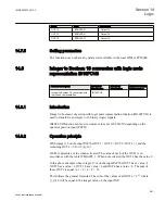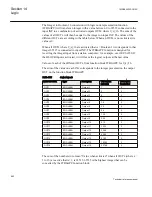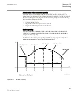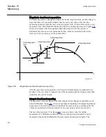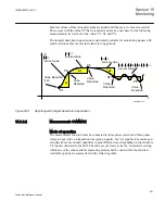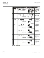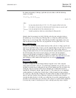
the measured quantity. Filtering is performed in accordance with the following
recursive formula:
(1
)
Old
Calculated
X
k X
k X
= ×
+ -
×
EQUATION1407 V1 EN
(Equation 180)
where:
X
is a new measured value (that is P, Q, S, V, I or PF) to be given out from the function
X
Old
is the measured value given from the measurement function in previous execution cycle
X
Calculated
is the new calculated value in the present execution cycle
k
is settable parameter by the end user which influence the filter properties
Default value for parameter
k
is 0.00. With this value the new calculated value is
immediately given out without any filtering (that is, without any additional delay).
When
k
is set to value bigger than 0, the filtering is enabled. Appropriate value of
k
shall be determined separately for every application. Some typical value for
k
=0.14.
Zero point clamping
In order to avoid erroneous measurements when either current or voltage signal is not
present, it is possible for the end user to set the magnitude
IGenZeroDb
level for current
and voltage measurement
VGenZeroDb
is forced to zero. When either current or
voltage measurement is forced to zero automatically the measured values for power (P,
Q and S) and power factor are forced to zero as well. Since the measurement
supervision functionality, included in CVMMXN, is using these values the zero
clamping will influence the subsequent supervision (observe the possibility to do zero
point clamping within measurement supervision, see section
).
Compensation facility
In order to compensate for small magnitude and angular errors in the complete
measurement chain (CT error, VT error, IED input transformer errors and so on.) it is
possible to perform on site calibration of the power measurement. This is achieved by
setting the complex constant which is then internally used within the function to
multiply the calculated complex apparent power S. This constant is set as magnitude
(setting parameter
PowMagFact
, default value 1.000) and angle (setting parameter
PowAngComp
, default value 0.0 degrees). Default values for these two parameters are
done in such way that they do not influence internally calculated value (complex
constant has default value 1). In this way calibration, for specific operating range (for
example, around rated power) can be done at site. However, to perform this calibration
it is necessary to have an external power meter with high accuracy class available.
1MRK505222-UUS C
Section 15
Monitoring
905
Technical reference manual
Содержание Relion 670 series
Страница 1: ...Relion 670 series Line differential protection RED670 ANSI Technical reference manual...
Страница 2: ......
Страница 40: ...34...
Страница 50: ...44...
Страница 60: ...54...
Страница 126: ...120...
Страница 384: ...378...
Страница 496: ...490...
Страница 556: ...550...
Страница 602: ...596...
Страница 620: ...614...
Страница 794: ...788...
Страница 864: ...858...
Страница 988: ...982...
Страница 998: ...992...
Страница 1084: ...1078...
Страница 1164: ...1158...
Страница 1168: ...1162...
Страница 1170: ...1MRK002802 AB 1 670 1 2 PG ANSI V1 EN Section 21 1MRK505222 UUS C Connection diagrams 1164 Technical reference manual...
Страница 1171: ...1MRK002802 AB 2 670 1 2 PG ANSI V1 EN 1MRK505222 UUS C Section 21 Connection diagrams 1165 Technical reference manual...
Страница 1172: ...1MRK002802 AB 3 670 1 2 PG ANSI V1 EN Section 21 1MRK505222 UUS C Connection diagrams 1166 Technical reference manual...
Страница 1173: ...1MRK002802 AB 4 670 1 2 PG ANSI V1 EN 1MRK505222 UUS C Section 21 Connection diagrams 1167 Technical reference manual...
Страница 1174: ...1MRK002802 AB 5 670 1 2 ANSI V1 EN Section 21 1MRK505222 UUS C Connection diagrams 1168 Technical reference manual...
Страница 1175: ...1MRK002802 AB 6 670 1 2 ANSI V1 EN 1MRK505222 UUS C Section 21 Connection diagrams 1169 Technical reference manual...
Страница 1176: ...1MRK002802 AB 7 670 1 2 ANSI V1 EN Section 21 1MRK505222 UUS C Connection diagrams 1170 Technical reference manual...
Страница 1177: ...1MRK002802 AB 8 670 1 2 ANSI V1 EN 1MRK505222 UUS C Section 21 Connection diagrams 1171 Technical reference manual...
Страница 1178: ...1MRK002802 AB 9 670 1 2 ANSI V1 EN Section 21 1MRK505222 UUS C Connection diagrams 1172 Technical reference manual...
Страница 1179: ...1MRK002802 AB 10 670 1 2 ANSI V1 EN 1MRK505222 UUS C Section 21 Connection diagrams 1173 Technical reference manual...
Страница 1180: ...1MRK002802 AB 11 670 1 2 ANSI V1 EN Section 21 1MRK505222 UUS C Connection diagrams 1174 Technical reference manual...
Страница 1181: ...1MRK002802 AB 12 670 1 2 ANSI V1 EN 1MRK505222 UUS C Section 21 Connection diagrams 1175 Technical reference manual...
Страница 1182: ...1MRK002802 AB 13 670 1 2 ANSI V1 EN Section 21 1MRK505222 UUS C Connection diagrams 1176 Technical reference manual...
Страница 1183: ...1MRK002802 AB 14 670 1 2 ANSI V1 EN 1MRK505222 UUS C Section 21 Connection diagrams 1177 Technical reference manual...
Страница 1184: ...1MRK002802 AB 15 670 1 2 ANSI V1 EN Section 21 1MRK505222 UUS C Connection diagrams 1178 Technical reference manual...
Страница 1220: ...1214...
Страница 1230: ...1224...
Страница 1231: ...1225...

