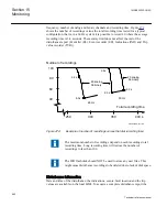


For each of the analog signals,
Operation
=
Enabled
means that it is recorded by the
disturbance recorder. The trigger is independent of the setting of
Operation
, and
triggers even if operation is set to
Disabled
. Both undervoltage and overvoltage can be
used as trigger conditions. The same applies for the current signals.
If
Operation
=
Disabled
, no waveform (samples) will be recorded and reported in
graph. However, Trip value, pre-fault and fault value will be recorded and reported.
The input channel can still be used to trig the disturbance recorder.
If
Operation
=
Enabled
, waveform (samples) will also be recorded and reported in graph.
The analog signals are presented only in the disturbance recording, but they affect the
entire disturbance report when being used as triggers.
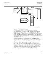
Binary signals
Up to 96 binary signals can be selected to be handled by disturbance report. The
signals can be selected from internal logical and binary input signals. A binary signal is
selected to be recorded when:
•
the corresponding function block is included in the configuration
•
the signal is connected to the input of the function block
Each of the 96 signals can be selected as a trigger of the disturbance report (
Operation
=
Operation—>TrigDR =Disabled
). A binary signal can be selected to activate the red
LED on the local HMI (
SetLED
=
Enabled
/
Disabled
).
The selected signals are presented in the event recorder, sequential of events and the
disturbance recording. But they affect the whole disturbance report when they are used
as triggers. The indications are also selected from these 96 signals with local HMI
IndicationMask=Show/Hide
.
Trigger signals
The trigger conditions affect the entire disturbance report, except the sequential of
events, which runs continuously. As soon as at least one trigger condition is fulfilled, a
complete disturbance report is recorded. On the other hand, if no trigger condition is
fulfilled, there is no disturbance report, no indications, and so on. This implies the
importance of choosing the right signals as trigger conditions.
A trigger can be of type:
•
Manual trigger
•
Binary-signal trigger
•
Analog-signal trigger (over/under function)
Section 15
1MRK505222-UUS C
Monitoring
956
Technical reference manual
Содержание Relion 670 series
Страница 1: ...Relion 670 series Line differential protection RED670 ANSI Technical reference manual...
Страница 2: ......
Страница 40: ...34...
Страница 50: ...44...
Страница 60: ...54...
Страница 126: ...120...
Страница 384: ...378...
Страница 496: ...490...
Страница 556: ...550...
Страница 602: ...596...
Страница 620: ...614...
Страница 794: ...788...
Страница 864: ...858...
Страница 988: ...982...
Страница 998: ...992...
Страница 1084: ...1078...
Страница 1164: ...1158...
Страница 1168: ...1162...
Страница 1170: ...1MRK002802 AB 1 670 1 2 PG ANSI V1 EN Section 21 1MRK505222 UUS C Connection diagrams 1164 Technical reference manual...
Страница 1171: ...1MRK002802 AB 2 670 1 2 PG ANSI V1 EN 1MRK505222 UUS C Section 21 Connection diagrams 1165 Technical reference manual...
Страница 1172: ...1MRK002802 AB 3 670 1 2 PG ANSI V1 EN Section 21 1MRK505222 UUS C Connection diagrams 1166 Technical reference manual...
Страница 1173: ...1MRK002802 AB 4 670 1 2 PG ANSI V1 EN 1MRK505222 UUS C Section 21 Connection diagrams 1167 Technical reference manual...
Страница 1174: ...1MRK002802 AB 5 670 1 2 ANSI V1 EN Section 21 1MRK505222 UUS C Connection diagrams 1168 Technical reference manual...
Страница 1175: ...1MRK002802 AB 6 670 1 2 ANSI V1 EN 1MRK505222 UUS C Section 21 Connection diagrams 1169 Technical reference manual...
Страница 1176: ...1MRK002802 AB 7 670 1 2 ANSI V1 EN Section 21 1MRK505222 UUS C Connection diagrams 1170 Technical reference manual...
Страница 1177: ...1MRK002802 AB 8 670 1 2 ANSI V1 EN 1MRK505222 UUS C Section 21 Connection diagrams 1171 Technical reference manual...
Страница 1178: ...1MRK002802 AB 9 670 1 2 ANSI V1 EN Section 21 1MRK505222 UUS C Connection diagrams 1172 Technical reference manual...
Страница 1179: ...1MRK002802 AB 10 670 1 2 ANSI V1 EN 1MRK505222 UUS C Section 21 Connection diagrams 1173 Technical reference manual...
Страница 1180: ...1MRK002802 AB 11 670 1 2 ANSI V1 EN Section 21 1MRK505222 UUS C Connection diagrams 1174 Technical reference manual...
Страница 1181: ...1MRK002802 AB 12 670 1 2 ANSI V1 EN 1MRK505222 UUS C Section 21 Connection diagrams 1175 Technical reference manual...
Страница 1182: ...1MRK002802 AB 13 670 1 2 ANSI V1 EN Section 21 1MRK505222 UUS C Connection diagrams 1176 Technical reference manual...
Страница 1183: ...1MRK002802 AB 14 670 1 2 ANSI V1 EN 1MRK505222 UUS C Section 21 Connection diagrams 1177 Technical reference manual...
Страница 1184: ...1MRK002802 AB 15 670 1 2 ANSI V1 EN Section 21 1MRK505222 UUS C Connection diagrams 1178 Technical reference manual...
Страница 1220: ...1214...
Страница 1230: ...1224...
Страница 1231: ...1225...