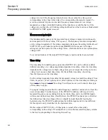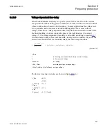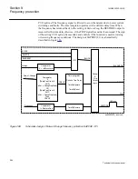
voltage is lower. If the frequency remains below the set value for a time period
corresponding to the chosen time delay, the corresponding trip signal is issued. To
avoid an unwanted trip due to uncertain frequency measurement at low voltage
magnitude, a voltage controlled blocking of the function is available, that is, if the
voltage is lower than the set blocking voltage
IntBlockLevel
the function is blocked and
no PICKUP or TRIP signal is issued.
9.1.2.1
Measurement principle
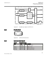
The fundamental frequency of the measured input voltage is measured continuously,
and compared with the set value,
PUFrequency
. The frequency function is dependent
on the voltage magnitude. If the voltage magnitude decreases the setting
IntBlockLevel
,
SAPTUF (81) gets blocked, and the output BLKDMAGN is issued. All voltage
settings are made in percent of the setting
VBase
, which should be set as a phase-phase
voltage in kV.
To avoid oscillations of the output PICKUP signal, a hysteresis has been included.
9.1.2.2
Time delay
The time delay for underfrequency protection SAPTUF (81) can be either a settable
definite time delay or a voltage magnitude dependent time delay, where the time delay
depends on the voltage level; a high voltage level gives a longer time delay and a low
voltage level causes a short time delay. For the definite time delay, the setting
TimeDlyOperate
sets the time delay.
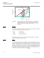
For the voltage dependent time delay the measured voltage level and the settings
VNom
,
VMin
,
Exponent
,
t_MaxTripDelay
and
t_MinTripDelay
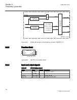
set the time delay according to
figure
. The setting
TimerOperation
is used to decide what type
of time delay to apply.
Trip signal issuing requires that the underfrequency condition continues for at least the
user set time delay
TimeDlyOperate
. If the PICKUP condition, with respect to the
measured frequency ceases during this user set delay time, and is not fulfilled again
within a user defined reset time,
TimeDlyReset
, the PICKUP output is reset, after that
the defined reset time has elapsed. Here it should be noted that after leaving the
hysteresis area, the PICKUP condition must be fulfilled again and it is not sufficient
for the signal to only return back to the hysteresis area.
On the output of SAPTUF (81) a 100ms pulse is issued, after a time delay
corresponding to the setting of
TimeDlyRestore
, when the measured frequency returns
to the level corresponding to the setting
RestoreFreq
.
Section 9
1MRK505222-UUS C
Frequency protection
552
Technical reference manual
Содержание Relion 670 series
Страница 1: ...Relion 670 series Line differential protection RED670 ANSI Technical reference manual...
Страница 2: ......
Страница 40: ...34...
Страница 50: ...44...
Страница 60: ...54...
Страница 126: ...120...
Страница 384: ...378...
Страница 496: ...490...
Страница 556: ...550...
Страница 602: ...596...
Страница 620: ...614...
Страница 794: ...788...
Страница 864: ...858...
Страница 988: ...982...
Страница 998: ...992...
Страница 1084: ...1078...
Страница 1164: ...1158...
Страница 1168: ...1162...
Страница 1170: ...1MRK002802 AB 1 670 1 2 PG ANSI V1 EN Section 21 1MRK505222 UUS C Connection diagrams 1164 Technical reference manual...
Страница 1171: ...1MRK002802 AB 2 670 1 2 PG ANSI V1 EN 1MRK505222 UUS C Section 21 Connection diagrams 1165 Technical reference manual...
Страница 1172: ...1MRK002802 AB 3 670 1 2 PG ANSI V1 EN Section 21 1MRK505222 UUS C Connection diagrams 1166 Technical reference manual...
Страница 1173: ...1MRK002802 AB 4 670 1 2 PG ANSI V1 EN 1MRK505222 UUS C Section 21 Connection diagrams 1167 Technical reference manual...
Страница 1174: ...1MRK002802 AB 5 670 1 2 ANSI V1 EN Section 21 1MRK505222 UUS C Connection diagrams 1168 Technical reference manual...
Страница 1175: ...1MRK002802 AB 6 670 1 2 ANSI V1 EN 1MRK505222 UUS C Section 21 Connection diagrams 1169 Technical reference manual...
Страница 1176: ...1MRK002802 AB 7 670 1 2 ANSI V1 EN Section 21 1MRK505222 UUS C Connection diagrams 1170 Technical reference manual...
Страница 1177: ...1MRK002802 AB 8 670 1 2 ANSI V1 EN 1MRK505222 UUS C Section 21 Connection diagrams 1171 Technical reference manual...
Страница 1178: ...1MRK002802 AB 9 670 1 2 ANSI V1 EN Section 21 1MRK505222 UUS C Connection diagrams 1172 Technical reference manual...
Страница 1179: ...1MRK002802 AB 10 670 1 2 ANSI V1 EN 1MRK505222 UUS C Section 21 Connection diagrams 1173 Technical reference manual...
Страница 1180: ...1MRK002802 AB 11 670 1 2 ANSI V1 EN Section 21 1MRK505222 UUS C Connection diagrams 1174 Technical reference manual...
Страница 1181: ...1MRK002802 AB 12 670 1 2 ANSI V1 EN 1MRK505222 UUS C Section 21 Connection diagrams 1175 Technical reference manual...
Страница 1182: ...1MRK002802 AB 13 670 1 2 ANSI V1 EN Section 21 1MRK505222 UUS C Connection diagrams 1176 Technical reference manual...
Страница 1183: ...1MRK002802 AB 14 670 1 2 ANSI V1 EN 1MRK505222 UUS C Section 21 Connection diagrams 1177 Technical reference manual...
Страница 1184: ...1MRK002802 AB 15 670 1 2 ANSI V1 EN Section 21 1MRK505222 UUS C Connection diagrams 1178 Technical reference manual...
Страница 1220: ...1214...
Страница 1230: ...1224...
Страница 1231: ...1225...

