
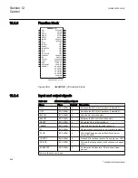


12.3.2
Principle of operation
A bay can handle, for example a power line, a transformer, a reactor, or a capacitor
bank. The different primary apparatuses within the bay can be controlled via the
apparatus control function directly by the operator or indirectly by automatic sequences.
Because a primary apparatus can be allocated to many functions within a Substation
Automation system, the object-oriented approach with a function module that handles
the interaction and status of each process object ensures consistency in the process
information used by higher-level control functions.
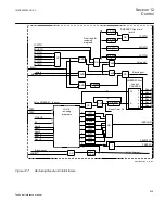
Primary apparatuses such as breakers and disconnectors are controlled and supervised
by one software module (SCSWI) each. Because the number and type of signals
connected to a breaker and a disconnector are almost the same, the same software is
used to handle these two types of apparatuses.
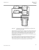
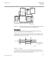
The software module is connected to the physical process in the switchyard via an
interface module by means of a number of digital inputs and outputs. One type of
interface module is intended for a circuit breaker (SXCBR) and another type is
intended for a disconnector or grounding switch (SXSWI). Four types of function
blocks are available to cover most of the control and supervision within the bay. These
function blocks are interconnected to form a control function reflecting the switchyard
configuration. The total number used depends on the switchyard configuration. These
four types are:
•
Bay control QCBAY
•
Switch controller SCSWI
•
Circuit breaker SXCBR
•
Circuit switch SXSWI
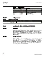
The three latter functions are logical nodes according to IEC 61850. The functions
Local Remote (LOCREM) and Local Remote Control (LOCREMCTRL), to handle the
local/remote switch, and the functions Bay reserve (QCRSV) and Reservation input
(RESIN), for the reservation function, also belong to the apparatus control function.
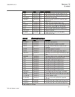
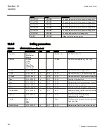
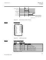
The principles of operation, function block, input and output signals and setting
parameters for all these functions are described below.
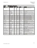
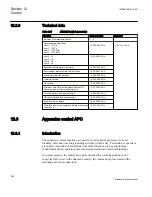
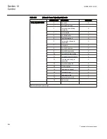
12.3.3
Error handling
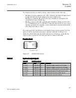
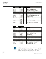
Depending on the error that occurs during the command sequence the error signal will
be set with a value. Table
describes vendor specific cause values in addition to
these specified in IEC 61850-8-1 standard. The list of values of the “cause” are in order
of priority. The values are available over the IEC 61850. An output L_CAUSE on the
function block for Switch controller (SCSWI), Circuit breaker (SXCBR) and Circuit
switch (SXSWI) indicates the latest value of the error during the command.
1MRK505222-UUS C
Section 12
Control
653
Technical reference manual
Содержание Relion 670 series
Страница 1: ...Relion 670 series Line differential protection RED670 ANSI Technical reference manual...
Страница 2: ......
Страница 40: ...34...
Страница 50: ...44...
Страница 60: ...54...
Страница 126: ...120...
Страница 384: ...378...
Страница 496: ...490...
Страница 556: ...550...
Страница 602: ...596...
Страница 620: ...614...
Страница 794: ...788...
Страница 864: ...858...
Страница 988: ...982...
Страница 998: ...992...
Страница 1084: ...1078...
Страница 1164: ...1158...
Страница 1168: ...1162...
Страница 1170: ...1MRK002802 AB 1 670 1 2 PG ANSI V1 EN Section 21 1MRK505222 UUS C Connection diagrams 1164 Technical reference manual...
Страница 1171: ...1MRK002802 AB 2 670 1 2 PG ANSI V1 EN 1MRK505222 UUS C Section 21 Connection diagrams 1165 Technical reference manual...
Страница 1172: ...1MRK002802 AB 3 670 1 2 PG ANSI V1 EN Section 21 1MRK505222 UUS C Connection diagrams 1166 Technical reference manual...
Страница 1173: ...1MRK002802 AB 4 670 1 2 PG ANSI V1 EN 1MRK505222 UUS C Section 21 Connection diagrams 1167 Technical reference manual...
Страница 1174: ...1MRK002802 AB 5 670 1 2 ANSI V1 EN Section 21 1MRK505222 UUS C Connection diagrams 1168 Technical reference manual...
Страница 1175: ...1MRK002802 AB 6 670 1 2 ANSI V1 EN 1MRK505222 UUS C Section 21 Connection diagrams 1169 Technical reference manual...
Страница 1176: ...1MRK002802 AB 7 670 1 2 ANSI V1 EN Section 21 1MRK505222 UUS C Connection diagrams 1170 Technical reference manual...
Страница 1177: ...1MRK002802 AB 8 670 1 2 ANSI V1 EN 1MRK505222 UUS C Section 21 Connection diagrams 1171 Technical reference manual...
Страница 1178: ...1MRK002802 AB 9 670 1 2 ANSI V1 EN Section 21 1MRK505222 UUS C Connection diagrams 1172 Technical reference manual...
Страница 1179: ...1MRK002802 AB 10 670 1 2 ANSI V1 EN 1MRK505222 UUS C Section 21 Connection diagrams 1173 Technical reference manual...
Страница 1180: ...1MRK002802 AB 11 670 1 2 ANSI V1 EN Section 21 1MRK505222 UUS C Connection diagrams 1174 Technical reference manual...
Страница 1181: ...1MRK002802 AB 12 670 1 2 ANSI V1 EN 1MRK505222 UUS C Section 21 Connection diagrams 1175 Technical reference manual...
Страница 1182: ...1MRK002802 AB 13 670 1 2 ANSI V1 EN Section 21 1MRK505222 UUS C Connection diagrams 1176 Technical reference manual...
Страница 1183: ...1MRK002802 AB 14 670 1 2 ANSI V1 EN 1MRK505222 UUS C Section 21 Connection diagrams 1177 Technical reference manual...
Страница 1184: ...1MRK002802 AB 15 670 1 2 ANSI V1 EN Section 21 1MRK505222 UUS C Connection diagrams 1178 Technical reference manual...
Страница 1220: ...1214...
Страница 1230: ...1224...
Страница 1231: ...1225...