


to each other can be separated with the line/s closest to the centre of the power swing
allowing the two systems to be stable as separated islands.
6.13.2
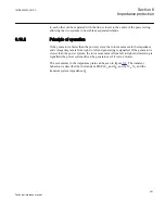
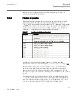
Principle of operation
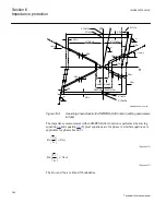
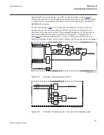
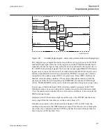
If the generator is faster than the power system, the rotor movement in the impedance
and voltage diagram is from right to left and generating is signalled. If the generator is
slower than the power system, the rotor movement is from left to right and motoring is
signalled (the power system drives the generator as if it were a motor).
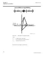
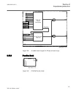
The movements in the impedance plain can be seen in figure
behaviour is described by the transient EMF's E
A
and E
B
, and by X'
d
, X
T
and the
transient system impedance Z
S
.
1MRK505222-UUS C
Section 6
Impedance protection
361
Technical reference manual
Содержание Relion 670 series
Страница 1: ...Relion 670 series Line differential protection RED670 ANSI Technical reference manual...
Страница 2: ......
Страница 40: ...34...
Страница 50: ...44...
Страница 60: ...54...
Страница 126: ...120...
Страница 384: ...378...
Страница 496: ...490...
Страница 556: ...550...
Страница 602: ...596...
Страница 620: ...614...
Страница 794: ...788...
Страница 864: ...858...
Страница 988: ...982...
Страница 998: ...992...
Страница 1084: ...1078...
Страница 1164: ...1158...
Страница 1168: ...1162...
Страница 1170: ...1MRK002802 AB 1 670 1 2 PG ANSI V1 EN Section 21 1MRK505222 UUS C Connection diagrams 1164 Technical reference manual...
Страница 1171: ...1MRK002802 AB 2 670 1 2 PG ANSI V1 EN 1MRK505222 UUS C Section 21 Connection diagrams 1165 Technical reference manual...
Страница 1172: ...1MRK002802 AB 3 670 1 2 PG ANSI V1 EN Section 21 1MRK505222 UUS C Connection diagrams 1166 Technical reference manual...
Страница 1173: ...1MRK002802 AB 4 670 1 2 PG ANSI V1 EN 1MRK505222 UUS C Section 21 Connection diagrams 1167 Technical reference manual...
Страница 1174: ...1MRK002802 AB 5 670 1 2 ANSI V1 EN Section 21 1MRK505222 UUS C Connection diagrams 1168 Technical reference manual...
Страница 1175: ...1MRK002802 AB 6 670 1 2 ANSI V1 EN 1MRK505222 UUS C Section 21 Connection diagrams 1169 Technical reference manual...
Страница 1176: ...1MRK002802 AB 7 670 1 2 ANSI V1 EN Section 21 1MRK505222 UUS C Connection diagrams 1170 Technical reference manual...
Страница 1177: ...1MRK002802 AB 8 670 1 2 ANSI V1 EN 1MRK505222 UUS C Section 21 Connection diagrams 1171 Technical reference manual...
Страница 1178: ...1MRK002802 AB 9 670 1 2 ANSI V1 EN Section 21 1MRK505222 UUS C Connection diagrams 1172 Technical reference manual...
Страница 1179: ...1MRK002802 AB 10 670 1 2 ANSI V1 EN 1MRK505222 UUS C Section 21 Connection diagrams 1173 Technical reference manual...
Страница 1180: ...1MRK002802 AB 11 670 1 2 ANSI V1 EN Section 21 1MRK505222 UUS C Connection diagrams 1174 Technical reference manual...
Страница 1181: ...1MRK002802 AB 12 670 1 2 ANSI V1 EN 1MRK505222 UUS C Section 21 Connection diagrams 1175 Technical reference manual...
Страница 1182: ...1MRK002802 AB 13 670 1 2 ANSI V1 EN Section 21 1MRK505222 UUS C Connection diagrams 1176 Technical reference manual...
Страница 1183: ...1MRK002802 AB 14 670 1 2 ANSI V1 EN 1MRK505222 UUS C Section 21 Connection diagrams 1177 Technical reference manual...
Страница 1184: ...1MRK002802 AB 15 670 1 2 ANSI V1 EN Section 21 1MRK505222 UUS C Connection diagrams 1178 Technical reference manual...
Страница 1220: ...1214...
Страница 1230: ...1224...
Страница 1231: ...1225...