


If the load compensated algorithms according to the above do not give a reliable
solution, a less accurate, non-compensated impedance model is used to calculate the
relative distance to the fault.
15.5.2.3
The non-compensated impedance model
In the non-compensated impedance model, I
A
line current is used instead of I
FA
fault
current:
A
1L
A
F
A
V
p Z
I
R I
= ×
× +
×
EQUATION1603 V1 EN
(Equation 194)
Where:
I
A
is according to table
The accuracy of the distance-to-fault calculation, using the non-compensated
impedance model, is influenced by the pre-fault load current. So, this method is only
used if the load compensated models do not function.
15.5.2.4
IEC 60870-5-103
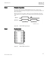
The communication protocol IEC 60870-5-103 may be used to poll fault location
information from the IED to a master (that is station HSI). There are two outputs that
must be connected to appropriate inputs on the function block I103StatFltDis,
FLTDISTX gives distance to fault (reactance, according the standard) and
CALCMADE gives a pulse (100 ms) when a result is obtainable on FLTDISTX output.
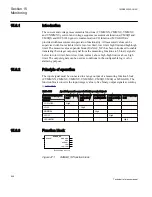
15.5.3
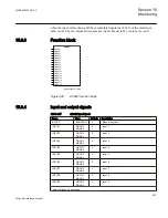
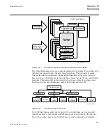
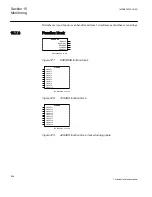
Function block
ANSI05000679-2-en.vsd
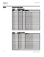
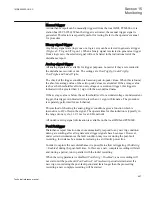
LMBRFLO
PHSEL_A*
PHSEL_B*
PHSEL_C*
CALCDIST*
FLTDISTX
CALCMADE
BCD_80
BCD_40
BCD_20
BCD_10
BCD_8
BCD_4
BCD_2
BCD_1
ANSI05000679 V2 EN
Figure 470:
FLO function block
1MRK505222-UUS C
Section 15
Monitoring
945
Technical reference manual
Содержание Relion 670 series
Страница 1: ...Relion 670 series Line differential protection RED670 ANSI Technical reference manual...
Страница 2: ......
Страница 40: ...34...
Страница 50: ...44...
Страница 60: ...54...
Страница 126: ...120...
Страница 384: ...378...
Страница 496: ...490...
Страница 556: ...550...
Страница 602: ...596...
Страница 620: ...614...
Страница 794: ...788...
Страница 864: ...858...
Страница 988: ...982...
Страница 998: ...992...
Страница 1084: ...1078...
Страница 1164: ...1158...
Страница 1168: ...1162...
Страница 1170: ...1MRK002802 AB 1 670 1 2 PG ANSI V1 EN Section 21 1MRK505222 UUS C Connection diagrams 1164 Technical reference manual...
Страница 1171: ...1MRK002802 AB 2 670 1 2 PG ANSI V1 EN 1MRK505222 UUS C Section 21 Connection diagrams 1165 Technical reference manual...
Страница 1172: ...1MRK002802 AB 3 670 1 2 PG ANSI V1 EN Section 21 1MRK505222 UUS C Connection diagrams 1166 Technical reference manual...
Страница 1173: ...1MRK002802 AB 4 670 1 2 PG ANSI V1 EN 1MRK505222 UUS C Section 21 Connection diagrams 1167 Technical reference manual...
Страница 1174: ...1MRK002802 AB 5 670 1 2 ANSI V1 EN Section 21 1MRK505222 UUS C Connection diagrams 1168 Technical reference manual...
Страница 1175: ...1MRK002802 AB 6 670 1 2 ANSI V1 EN 1MRK505222 UUS C Section 21 Connection diagrams 1169 Technical reference manual...
Страница 1176: ...1MRK002802 AB 7 670 1 2 ANSI V1 EN Section 21 1MRK505222 UUS C Connection diagrams 1170 Technical reference manual...
Страница 1177: ...1MRK002802 AB 8 670 1 2 ANSI V1 EN 1MRK505222 UUS C Section 21 Connection diagrams 1171 Technical reference manual...
Страница 1178: ...1MRK002802 AB 9 670 1 2 ANSI V1 EN Section 21 1MRK505222 UUS C Connection diagrams 1172 Technical reference manual...
Страница 1179: ...1MRK002802 AB 10 670 1 2 ANSI V1 EN 1MRK505222 UUS C Section 21 Connection diagrams 1173 Technical reference manual...
Страница 1180: ...1MRK002802 AB 11 670 1 2 ANSI V1 EN Section 21 1MRK505222 UUS C Connection diagrams 1174 Technical reference manual...
Страница 1181: ...1MRK002802 AB 12 670 1 2 ANSI V1 EN 1MRK505222 UUS C Section 21 Connection diagrams 1175 Technical reference manual...
Страница 1182: ...1MRK002802 AB 13 670 1 2 ANSI V1 EN Section 21 1MRK505222 UUS C Connection diagrams 1176 Technical reference manual...
Страница 1183: ...1MRK002802 AB 14 670 1 2 ANSI V1 EN 1MRK505222 UUS C Section 21 Connection diagrams 1177 Technical reference manual...
Страница 1184: ...1MRK002802 AB 15 670 1 2 ANSI V1 EN Section 21 1MRK505222 UUS C Connection diagrams 1178 Technical reference manual...
Страница 1220: ...1214...
Страница 1230: ...1224...
Страница 1231: ...1225...