•
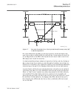
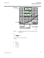
A pickup in one phase, gives a trip under the condition that the content of 2
nd
and
5
th
harmonic is below the set level for these harmonics. Otherwise it is blocked as
long as the harmonic is above the set level. However, when a line is energized the
current setting value
IdMinHigh
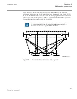
is used. Effectively this means that the line A-B-C
in figure
forms the characteristic.
•
Current values above the unrestrained limit gives a trip irrespective of any
presence of harmonics.
•
Classification of a fault as internal by the negative sequence fault discriminator,
will give a trip under the condition that a pickup has occurred in that phase. This
means that any harmonic blocking is then overridden. However, occurrence of
harmonics at the same time as the differential current is below the level
IdMinHigh
, will block a trip even though the fault is classified as internal. This
latter condition is to prevent unwanted trips when energizing a line tap transformer.
•
Classification of a fault as external by the negative sequence fault discriminator
will cause
IdMinHigh
to be used as the lower limit for the restrained characteristic
according to figure
. Cross blocking will also be activated in this situation.
Compensation for charging currents can be selected active or not by setting
ChargCurEnableYes
or
No
. The compensation works such that the fundamental
frequency differential current that is measured under steady state undisturbed
conditions, is identified and then subtracted making the resulting differential current
zero (or close to zero). This action is made separately for each phase. The magnitude of
the subtracted pre-fault currents in Amperes can be read at any time as the service
value ICHARGE.
Values of the pre-fault differential currents are not updated under disturbance
conditions. The updating process is resumed 50 ms after normal conditions have been
restored. Normal conditions are only considered if there are no pickup signals, neither
internal nor external fault is declared, the power system is symmetrical and so on.
It is thus obvious that the change in charging current that the fault causes by decreasing
the system voltage is not considered in the algorithm, a matter that is further discussed
in the application manual.
Note that all small pre-fault differential currents are subtracted, no matter what their
origin. Besides the true charging currents, the following currents are eliminated:
•
Small differential currents due to small errors (inequalities) of current transformers.
•
Small differential currents because of off-nominal load tap changer positions when
a power transformer is included in the protected zone.
•
Load currents of tap loads included in the protected zone.
1MRK505222-UUS C
Section 5
Differential protection
133
Technical reference manual
Содержание Relion 670 series
Страница 1: ...Relion 670 series Line differential protection RED670 ANSI Technical reference manual...
Страница 2: ......
Страница 40: ...34...
Страница 50: ...44...
Страница 60: ...54...
Страница 126: ...120...
Страница 384: ...378...
Страница 496: ...490...
Страница 556: ...550...
Страница 602: ...596...
Страница 620: ...614...
Страница 794: ...788...
Страница 864: ...858...
Страница 988: ...982...
Страница 998: ...992...
Страница 1084: ...1078...
Страница 1164: ...1158...
Страница 1168: ...1162...
Страница 1170: ...1MRK002802 AB 1 670 1 2 PG ANSI V1 EN Section 21 1MRK505222 UUS C Connection diagrams 1164 Technical reference manual...
Страница 1171: ...1MRK002802 AB 2 670 1 2 PG ANSI V1 EN 1MRK505222 UUS C Section 21 Connection diagrams 1165 Technical reference manual...
Страница 1172: ...1MRK002802 AB 3 670 1 2 PG ANSI V1 EN Section 21 1MRK505222 UUS C Connection diagrams 1166 Technical reference manual...
Страница 1173: ...1MRK002802 AB 4 670 1 2 PG ANSI V1 EN 1MRK505222 UUS C Section 21 Connection diagrams 1167 Technical reference manual...
Страница 1174: ...1MRK002802 AB 5 670 1 2 ANSI V1 EN Section 21 1MRK505222 UUS C Connection diagrams 1168 Technical reference manual...
Страница 1175: ...1MRK002802 AB 6 670 1 2 ANSI V1 EN 1MRK505222 UUS C Section 21 Connection diagrams 1169 Technical reference manual...
Страница 1176: ...1MRK002802 AB 7 670 1 2 ANSI V1 EN Section 21 1MRK505222 UUS C Connection diagrams 1170 Technical reference manual...
Страница 1177: ...1MRK002802 AB 8 670 1 2 ANSI V1 EN 1MRK505222 UUS C Section 21 Connection diagrams 1171 Technical reference manual...
Страница 1178: ...1MRK002802 AB 9 670 1 2 ANSI V1 EN Section 21 1MRK505222 UUS C Connection diagrams 1172 Technical reference manual...
Страница 1179: ...1MRK002802 AB 10 670 1 2 ANSI V1 EN 1MRK505222 UUS C Section 21 Connection diagrams 1173 Technical reference manual...
Страница 1180: ...1MRK002802 AB 11 670 1 2 ANSI V1 EN Section 21 1MRK505222 UUS C Connection diagrams 1174 Technical reference manual...
Страница 1181: ...1MRK002802 AB 12 670 1 2 ANSI V1 EN 1MRK505222 UUS C Section 21 Connection diagrams 1175 Technical reference manual...
Страница 1182: ...1MRK002802 AB 13 670 1 2 ANSI V1 EN Section 21 1MRK505222 UUS C Connection diagrams 1176 Technical reference manual...
Страница 1183: ...1MRK002802 AB 14 670 1 2 ANSI V1 EN 1MRK505222 UUS C Section 21 Connection diagrams 1177 Technical reference manual...
Страница 1184: ...1MRK002802 AB 15 670 1 2 ANSI V1 EN Section 21 1MRK505222 UUS C Connection diagrams 1178 Technical reference manual...
Страница 1220: ...1214...
Страница 1230: ...1224...
Страница 1231: ...1225...

