12.2.2.2
Auto-reclosing operation
Disabled and Enabled
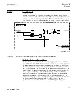
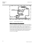
Operation of the automatic reclosing can be set to Off or On via the setting parameters
and through external control. With the setting
Operation
=
Enabled
, the function is
activated while with the setting
Operation
=
Disabled
the function is deactivated. With
the setting
Operation
=
External ctrl
, the activation/deactivation is made by input
signal pulses, for example, from a control system.
When the function is set
Enabled
and is operative the output SETON is activated
(high). Other input conditions such as 52a and CBREADY must also be fulfilled. At
this point the automatic recloser is prepared to start the reclosing cycle and the output
signal READY on the SMBRREC (79) function block is activated (high).
12.2.2.3
Auto-reclosing mode selection
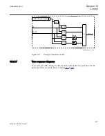
The Auto-reclosing mode is selected with setting
ARMode
=
3phase(0)
,
1/2/3ph(1)
,
1/2ph(2)
,
1ph+1*2ph(3)
,
1/2ph+1*3ph(4)
,
1ph+1*2/3ph(5)
. The selected mode can be
read as integer as per above list on output MODE.
As an alternative to setting the mode can be selected by connecting an integer, for
example from function block B16I to input MODEINT.
Following integers shall be used:
1=3phase
,
2=1/2/3ph
,
3=1/2ph
,
4=1ph+1*2ph
,
5=1/2ph+1*3ph
or
6=1ph+1*2/3ph
.
When INTZERO from Fixed signal function block is connected to the input
MODEINT the parameter setting selected will be valid.
12.2.2.4
Initiate auto-reclosing and conditions for initiation of a reclosing cycle
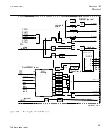
The usual way in which to initiate a reclosing cycle, or sequence, is to initiate it when a
line protection tripping has occurred, by applying a signal to the RI input. It should be
necessary to adjust three-phase auto-reclosing open time, (dead time) for different
power system configurations or during tripping at different protection stages, the input
RI_HS (reclose initiation of high-speed reclosing) can also be used.
For a new auto-reclosing cycle to be started, a number of conditions need to be met.
They are linked to dedicated inputs. The inputs are:
•
CBREADY: CB ready for a reclosing cycle, for example, charged operating gear
•
52a: to ensure that the CB was closed when the line fault occurred and initiation
was applied
•
No blocking or inhibit signal shall be present.
Section 12
1MRK505222-UUS C
Control
634
Technical reference manual
Содержание Relion 670 series
Страница 1: ...Relion 670 series Line differential protection RED670 ANSI Technical reference manual...
Страница 2: ......
Страница 40: ...34...
Страница 50: ...44...
Страница 60: ...54...
Страница 126: ...120...
Страница 384: ...378...
Страница 496: ...490...
Страница 556: ...550...
Страница 602: ...596...
Страница 620: ...614...
Страница 794: ...788...
Страница 864: ...858...
Страница 988: ...982...
Страница 998: ...992...
Страница 1084: ...1078...
Страница 1164: ...1158...
Страница 1168: ...1162...
Страница 1170: ...1MRK002802 AB 1 670 1 2 PG ANSI V1 EN Section 21 1MRK505222 UUS C Connection diagrams 1164 Technical reference manual...
Страница 1171: ...1MRK002802 AB 2 670 1 2 PG ANSI V1 EN 1MRK505222 UUS C Section 21 Connection diagrams 1165 Technical reference manual...
Страница 1172: ...1MRK002802 AB 3 670 1 2 PG ANSI V1 EN Section 21 1MRK505222 UUS C Connection diagrams 1166 Technical reference manual...
Страница 1173: ...1MRK002802 AB 4 670 1 2 PG ANSI V1 EN 1MRK505222 UUS C Section 21 Connection diagrams 1167 Technical reference manual...
Страница 1174: ...1MRK002802 AB 5 670 1 2 ANSI V1 EN Section 21 1MRK505222 UUS C Connection diagrams 1168 Technical reference manual...
Страница 1175: ...1MRK002802 AB 6 670 1 2 ANSI V1 EN 1MRK505222 UUS C Section 21 Connection diagrams 1169 Technical reference manual...
Страница 1176: ...1MRK002802 AB 7 670 1 2 ANSI V1 EN Section 21 1MRK505222 UUS C Connection diagrams 1170 Technical reference manual...
Страница 1177: ...1MRK002802 AB 8 670 1 2 ANSI V1 EN 1MRK505222 UUS C Section 21 Connection diagrams 1171 Technical reference manual...
Страница 1178: ...1MRK002802 AB 9 670 1 2 ANSI V1 EN Section 21 1MRK505222 UUS C Connection diagrams 1172 Technical reference manual...
Страница 1179: ...1MRK002802 AB 10 670 1 2 ANSI V1 EN 1MRK505222 UUS C Section 21 Connection diagrams 1173 Technical reference manual...
Страница 1180: ...1MRK002802 AB 11 670 1 2 ANSI V1 EN Section 21 1MRK505222 UUS C Connection diagrams 1174 Technical reference manual...
Страница 1181: ...1MRK002802 AB 12 670 1 2 ANSI V1 EN 1MRK505222 UUS C Section 21 Connection diagrams 1175 Technical reference manual...
Страница 1182: ...1MRK002802 AB 13 670 1 2 ANSI V1 EN Section 21 1MRK505222 UUS C Connection diagrams 1176 Technical reference manual...
Страница 1183: ...1MRK002802 AB 14 670 1 2 ANSI V1 EN 1MRK505222 UUS C Section 21 Connection diagrams 1177 Technical reference manual...
Страница 1184: ...1MRK002802 AB 15 670 1 2 ANSI V1 EN Section 21 1MRK505222 UUS C Connection diagrams 1178 Technical reference manual...
Страница 1220: ...1214...
Страница 1230: ...1224...
Страница 1231: ...1225...

