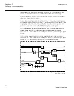
protection including a channel transmission time, can be achieved. This short operate
time enables rapid autoreclosing function after the fault clearance.
The communication logic module for directional residual current protection enables
blocking as well as permissive under/overreaching schemes. The logic can also be
supported by additional logic for weak-end infeed and current reversal, included in
Current reversal and weak-end infeed logic for residual overcurrent protection
(ECRWPSCH, 85) function.
13.5.2
Principle of operation
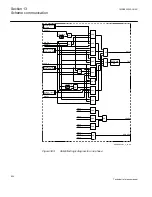
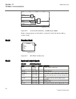
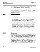
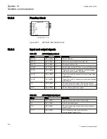
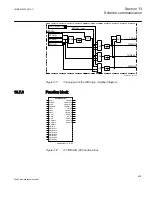
The four step directional residual overcurrent protection EF4PTOC (51N/67N) is
configured to give input information, that is directional fault detection signals, to the
ECPSCH (85) logic:
•
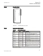
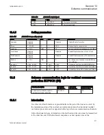
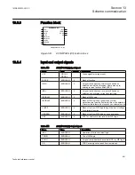
Input signal PLTR_CRD is used for tripping of the communication scheme,
normally the pickup signal of a forward overreaching step of STFW.
•
Input signal CS_STOP is used for sending block signal in the blocking
communication scheme, normally thepickup signal of a reverse overreaching step
of STRV.
•
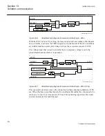
Input signal CSUR is used for sending permissive signal in the underreaching
permissive communication scheme, normally the pickup signal of a forward
underreaching step of STINn, where n corresponds to the underreaching step.
•
Input signal CSOR is used for sending permissive signal in the overreaching
permissive communication scheme, normally the pickup signal of a forward
overreaching step of STINn, where n corresponds to the overreaching step.
In addition to this a signal from the autoreclosing function should be configured to the
BLKCS input for blocking of the function at a single phase reclosing cycle.
13.5.2.1
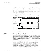
Blocking scheme
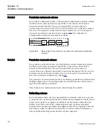
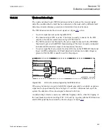
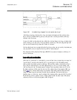
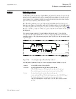
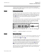
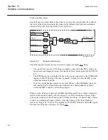
In the blocking scheme a signal is sent to the other line end if the directional element
detects a ground fault in the reverse direction. When the forward directional element
operates, it trips after a short time delay if no blocking signal is received from the
opposite line end. The time delay, normally 30 – 40 ms, depends on the
communication transmission time and a chosen safety margin.
One advantage of the blocking scheme is that only one channel (carrier frequency) is
needed if the ratio of source impedances at both end is approximately equal for zero
and positive sequence source impedances, the channel can be shared with the
impedance measuring system, if that system also works in the blocking mode. The
communication signal is transmitted on a healthy line and no signal attenuation will
occur due to the fault.
Section 13
1MRK505222-UUS C
Scheme communication
812
Technical reference manual
Содержание Relion 670 series
Страница 1: ...Relion 670 series Line differential protection RED670 ANSI Technical reference manual...
Страница 2: ......
Страница 40: ...34...
Страница 50: ...44...
Страница 60: ...54...
Страница 126: ...120...
Страница 384: ...378...
Страница 496: ...490...
Страница 556: ...550...
Страница 602: ...596...
Страница 620: ...614...
Страница 794: ...788...
Страница 864: ...858...
Страница 988: ...982...
Страница 998: ...992...
Страница 1084: ...1078...
Страница 1164: ...1158...
Страница 1168: ...1162...
Страница 1170: ...1MRK002802 AB 1 670 1 2 PG ANSI V1 EN Section 21 1MRK505222 UUS C Connection diagrams 1164 Technical reference manual...
Страница 1171: ...1MRK002802 AB 2 670 1 2 PG ANSI V1 EN 1MRK505222 UUS C Section 21 Connection diagrams 1165 Technical reference manual...
Страница 1172: ...1MRK002802 AB 3 670 1 2 PG ANSI V1 EN Section 21 1MRK505222 UUS C Connection diagrams 1166 Technical reference manual...
Страница 1173: ...1MRK002802 AB 4 670 1 2 PG ANSI V1 EN 1MRK505222 UUS C Section 21 Connection diagrams 1167 Technical reference manual...
Страница 1174: ...1MRK002802 AB 5 670 1 2 ANSI V1 EN Section 21 1MRK505222 UUS C Connection diagrams 1168 Technical reference manual...
Страница 1175: ...1MRK002802 AB 6 670 1 2 ANSI V1 EN 1MRK505222 UUS C Section 21 Connection diagrams 1169 Technical reference manual...
Страница 1176: ...1MRK002802 AB 7 670 1 2 ANSI V1 EN Section 21 1MRK505222 UUS C Connection diagrams 1170 Technical reference manual...
Страница 1177: ...1MRK002802 AB 8 670 1 2 ANSI V1 EN 1MRK505222 UUS C Section 21 Connection diagrams 1171 Technical reference manual...
Страница 1178: ...1MRK002802 AB 9 670 1 2 ANSI V1 EN Section 21 1MRK505222 UUS C Connection diagrams 1172 Technical reference manual...
Страница 1179: ...1MRK002802 AB 10 670 1 2 ANSI V1 EN 1MRK505222 UUS C Section 21 Connection diagrams 1173 Technical reference manual...
Страница 1180: ...1MRK002802 AB 11 670 1 2 ANSI V1 EN Section 21 1MRK505222 UUS C Connection diagrams 1174 Technical reference manual...
Страница 1181: ...1MRK002802 AB 12 670 1 2 ANSI V1 EN 1MRK505222 UUS C Section 21 Connection diagrams 1175 Technical reference manual...
Страница 1182: ...1MRK002802 AB 13 670 1 2 ANSI V1 EN Section 21 1MRK505222 UUS C Connection diagrams 1176 Technical reference manual...
Страница 1183: ...1MRK002802 AB 14 670 1 2 ANSI V1 EN 1MRK505222 UUS C Section 21 Connection diagrams 1177 Technical reference manual...
Страница 1184: ...1MRK002802 AB 15 670 1 2 ANSI V1 EN Section 21 1MRK505222 UUS C Connection diagrams 1178 Technical reference manual...
Страница 1220: ...1214...
Страница 1230: ...1224...
Страница 1231: ...1225...

