


EDA-Z5008, Z5020 & Z5100 – Technical Manual
ZPControlTechMan_r105
_____________________________________________________________________________________________________
40
10.2 - View Detailed Verify Information for a Single Device – service and commissioning users
1.Main Menu>>5.Verify Table>>1.View Table>>2.View Detailed
From the
‘Verify Table’
menu, select
‘1-View Table’
. Select
‘2View
Detailed’
. Press
Enter
to continue. Using the
↑
and
↓
keys select
number of the device you wish to view details of and press
→
.
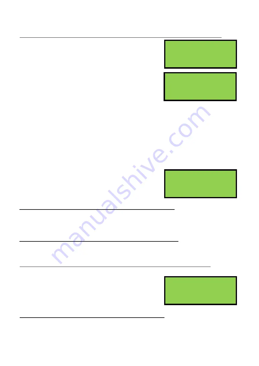
Screen 1
Dev: The device number for which the information is displayed.
Count: The time in seconds since the device last transmitted.
Max: The longest interval between two successfully received
transmissions. This gives a good indication of how the
device is performing. As a device transmits every 60 seconds, if the value is around 60, it has
never missed a transmission, but if it is at 180 then two transmissions have been missed.
RSSI: The average signal strength of the device received at the main control panel, on a scale of -20 to
+20. Any device with a strength above 0 will normally have satisfactory performance.
Ant:
The antenna number for the signal being received.
Fail:
The number of times the device has failed to transmit within the programmed period of time.
Local: YES means the device is assigned to the selected antenna. NO means the device is assigned to
another antenna. On a single panel, single antenna system this will always read YES.
Last: The RSSI of the last received transmission.
Screen 2
By using the
→
cursor key the screen opposite will appear. This
screen details the number of times the device has failed to
transmit within the time period shown. This information is for the
history of the device since the verify table or device was cleared.
View the Local Verify Information for All Devices – commissioning users
1.Main Menu>>5.Verify Table>>1.View Table>>3.View System>>1.View Local
This will display the local information for each device. The strengths shown are between the device and
the antenna to which it is assigned.
View the Verify Information for the Whole System – commissioning users
1.Main Menu>>5.Verify Table>>1.View Table>>3.View System>>2.View All
Allows the user to select a panel or antenna and see the count and RSSI values for any device.
10.3 - Clear the Verify Information for a Single Device – service and commissioning users
1.Main Menu>>5.Verify Table>>2.Clear Table>>1.Clear One Device
It is often necessary to clear the verify table. If devices have been
moved around the building or devices have been replaced, then
any historical information needs to be deleted and any new
information recorded. Use the cursor keys to select which device
to clear, and press
Enter
to confirm.
Clear the Complete Verify Table – service and commissioning users
1.Main Menu>>5.Verify Table>>2.Clear Table>>2.Clear All
This option will clear the verify information for all devices on the system. Press
Enter
to confirm.
RSSI limits
Min -20, Max +20
(Less than 0 is LOW)
ENTER to continue
Dev:001
Ant:001
Count:00055 Fail:000
Max:00120 Local:YES
RSSI:+20 Last:+20
Dev:001
Ant:01↕
>120 >150 >180 >240
002 001 000 000
Select Device 001↕
HEAT/SOUNDER
Use ← → keys


