ST950S Plus+ Installation and Commissioning Manual
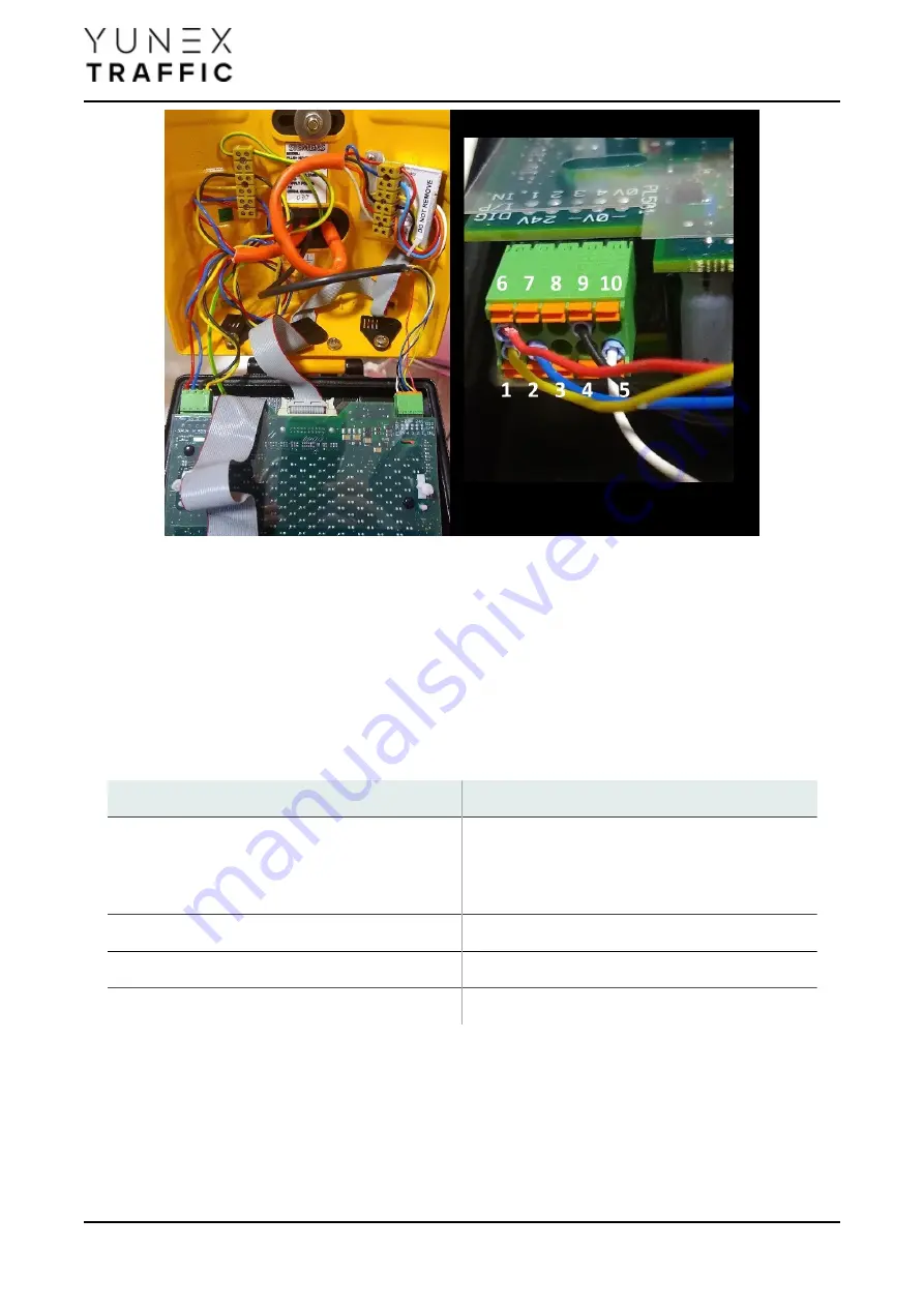
Figure 53. Example connection of AGD direct to Nearside PCB
If the cable used is larger or less flexible, it is possible to utilise the left-hand terminal block to terminate
the larger cable, and take the signals to PL501 on the Nearside using small separate wires. It is
acceptable to use two wires into one terminal on the left rear terminal block or on the PL501 Nearside
connector, if required due to the number of AGD sensors connected. (12W is available at 24Vdc,
normally a maximum of 3 AGD detectors).
Table 36. AGD to Nearside Connection Detail
AGD Connection
Nearside Connection
Detection (yellow or blue)
1, 2, or 3: IN1, IN2 or IN3
Default IN1,2,3 mapped to VEH, ONC, and KBS
Common (white)
5,8,9 or 10: 0V (power or signal return)
+24V (red)
6 or 7: +24V
0V (black)
5,8,9 or 10: 0V (power or signal return)
4.8.4. Parts
3m cable kit with inline connector 667/1/31960/104
Depending on application
Page 95


