


6-27
IM AQ6373-01EN
W
aveform Display
1
2
3
4
5
6
7
8
9
10
11
App
Index
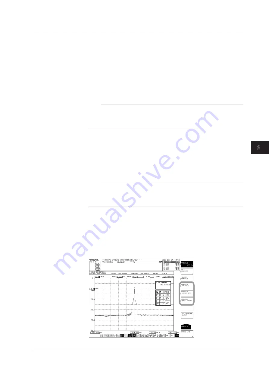
Using Moving Markers to Set the Center Wavelength to Be Measured, the
Zoom Center Wavelength, and the Reference Level
Setting the Moving Marker Wavelength as the Measurement Center
Wavelength
With the moving marker displayed, press the
MARKER-> CENTER
soft key. The
measured center wavelength setting screen and setting value are displayed.
For information on the center wavelength, see section 5.5, “Center Wavelength
Setting.”
The measurement center wavelength can be set by continuing in the DATA ENTRY section.
Note
The MARKER->CENTER soft key cannot be used under the following conditions.
• When the moving marker is OFF.
• When both SPLIT screens are on HOLD.
• When the measurement data SPAN is 0 nm.
Setting the Moving Marker Wavelength as the Zoom Center Wavelength
With the moving marker displayed, press the
MARKER-> ZOOM CTR
soft key.
The zoom center wavelength setting screen and setting value are displayed. For
information on the zoom center wavelength, see section 6.1, “Zooming In/Out on
a Wavelength.”
The zoom center wavelength can be set by continuing from the DATA ENTRY section.
Note
The MARKER->ZOOM CTR soft key cannot be used under the following conditions.
• When the moving marker is OFF.
• When both SPLIT screens are on HOLD.
• When the measurement data SPAN is 0 nm.
Setting the Moving Marker Level to the Reference Level
With the moving marker displayed, press the
MARKER-> REF LEVEL
soft key.
The reference level setting screen and setting value are displayed. For information
on the reference level, see section 5.4, “Reference Level Setting.” You can also
rewrite the currently displayed waveform according to the modified reference
level.
The measurement center wavelength can be set by continuing in the DATA ENTRY section.
6.8 Marker Display