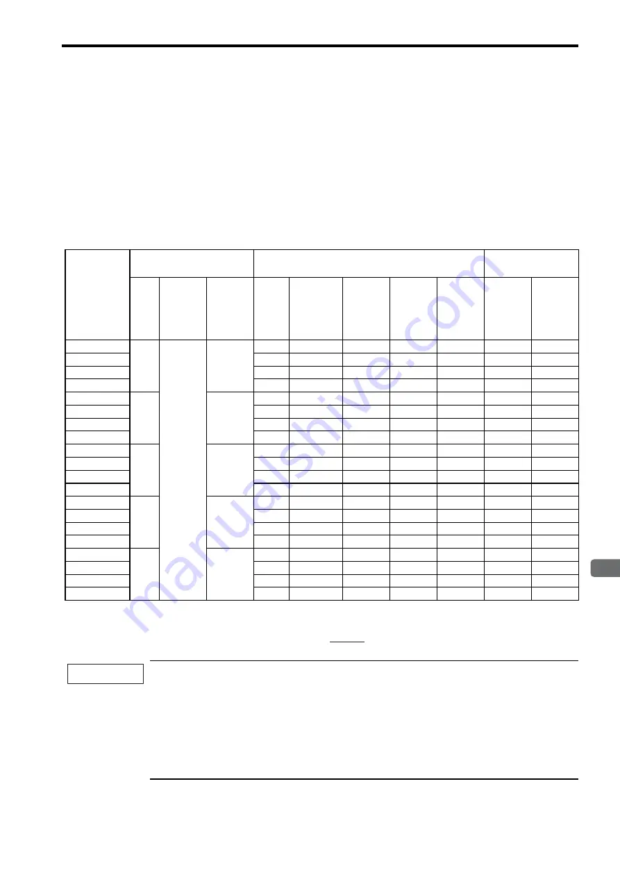
3.2 Ratings and Specifications of SGMPH (3000 min
-1
)
3-13
3
Servomotor Specifications and Dimensional Drawings
3.2.2 SGMPH Servomotors With Standard Backlash Gears
* 1. Maximum motor speed is up to 4000 min
-1
at the shaft.
* 2. Gear output torque is expressed using the following equation.
(Gear output torque) = (servomotor output torque)
×
×
(efficiency)
The no-load torque for a servomotor with gears is high immediately after the servomotor starts, and it then
decreases and becomes stable a few minutes later. This is a common phenomenon caused by grease being
circulated in the gear and not by a faulty gear.
The speed control range of SERVOPACKs in the
Σ
-II series is 1:5000. When using servomotors at
extremely low speeds (for example, 0.02 min
-1
max. at the gear output shaft) or when using servomotors
with one pulse feed reference for extended periods and in other situations that are less than optimum, the
lubrication of the gear bearing may be insufficient. This may cause deterioration of the bearing or increase
the load ratio.
Contact your Yaskawa representative if you are using your servomotor under such conditions.
• Time Rating: Continuous
• Thermal Class: B
• Vibration Class: 15
μ
m or below
• Withstand Voltage:
100V, 200V Servomotors: 1500 VAC for one minute
• Insulation Resistance: 500 VDC, 10 M
Ω
min.
• Enclosure: Totally enclosed, self-cooled, IP55 (except
for shaft opening)
• Surrounding Air Temperature: 0 to 40
°
C
• Ambient Humidity: 20% to 80% (no condensation)
• Excitation: Permanent magnet
• Drive Method: Direct drive
• Mounting: Flange-mounted
• Backlash: 15 min max.
• Gear Mechanism: Planetary gear mechanism
• Gear Rotation Direction: Same direction as servomotor
Servomotor
Model
SGMPH-
Servomotor
Gear Output
Moment of Inertia J
×
10
-4
kg·m
2
Out-
put
W
Rated
Speed
min
-1
Rated
Torque
N
x
m
Gear
Ratio
Rated
Torque/
Effi-
ciency
∗
2
N·m/%
Instanta-
neous
Peak
Torque
N·m
Rated
Speed
min
-1
Max.
Speed
∗
1
min
-1
Motor +
Gears
Gears
01
J1
100
3000
0.318
1/5
1.27/80
4.32
600
800
0.112
0.063
01
J3
3/31
2.63/80
8.88
290
387
0.067
0.018
01
JC
1/21
5.34/80
18.1
143
190
0.084
0.035
01
J7
1/33
8.40/80
28.4
91
121
0.070
0.021
02
J1
200
0.637
1/5
2.55/80
8.6
600
800
0.386
0.193
02
J3
3/31
5.27/80
17.8
290
387
0.283
0.090
02
JC
1/21
10.7/80
36.1
143
190
0.298
0.105
02
J7
1/33
16.8/80
56.7
91
121
0.268
0.075
04
J1
400
1.27
1/5
5.08/80
17.2
600
800
0.524
0.193
04
J3
3/31
10.5/80
35.5
290
387
0.511
0.180
04
JC
1/21
21.3/80
72.2
143
190
0.561
0.230
04
J7
1/33
33.5/80
113
91
121
0.496
0.165
08
J1
750
2.39
1/5
9.56/80
32
600
800
2.55
0.450
08
J3
3/31
19.8/80
66.6
290
387
2.53
0.425
08
JC
1/21
40.2/80
134
143
190
2.58
0.475
08
J7
1/33
63.1/80
213
91
121
2.4
0.300
15
J1
1500
4.77
1/5
19.1/80
64.4
600
800
4.97
0.950
15
J3
1/11
42.5/80
144
269
359
5.27
1.250
15
JC
1/21
80.1/80
270
143
190
5.33
1.300
15
J7
1/33
126/80
425
91
121
4.82
0.800
1
gear ratio
( )
IMPORTANT
Summary of Contents for Sigma-II Series
Page 384: ...8 3 8 Operation...


