


TECHNICAL DATA
XEROX DOCUMENT BINDER 120 OPERATOR MANUAL
8-3
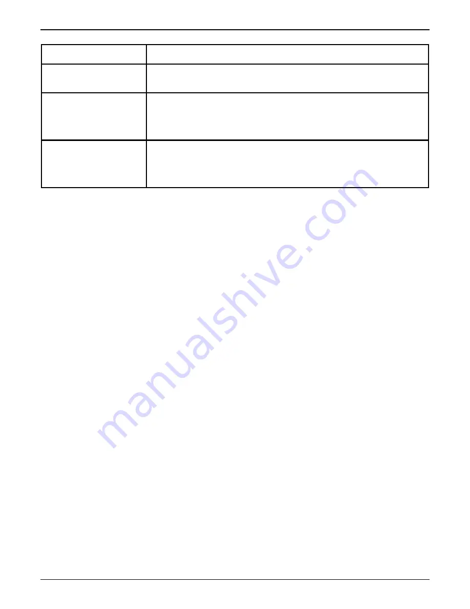
Machine weight
Approximately 475 lbs (216 kg) with cassettes
Noise level
?
Stand-by: 43.4 decibels
?
Run: 62.3 decibels
Power consumption
?
Warm up: 800 watts
?
Standby: 237 watts
?
Operation: 324 watts
?
Energy Saver: 31 watts
Heat output
?
Warm up: 2730 BTU per hour
?
Standby: 809 BTU per hour
?
Operation: 1106 BTU per hour
?
Energy Saver: 108 BTU per hour
Summary of Contents for Document Binder 120
Page 1: ...XEROX Xerox Document Binder 120 Operator Manual January 1999 701P99911 ...
Page 20: ...TECHNICAL DATA 8 8 XEROX DOCUMENT BINDER 120 OPERATOR MANUAL Notes ...
Page 38: ...PROBLEM SOLVING XEROX DOCUMENT BINDER 120 OPERATOR MANUAL 7 19 Notes ...
Page 39: ...PROBLEM SOLVING 7 20 XEROX DOCUMENT BINDER 120 OPERATOR MANUAL Notes ...
Page 42: ...CARE 6 4 XEROX DOCUMENT BINDER 120 OPERATOR MANUAL Notes ...
Page 48: ...CUSTOMIZING YOUR BINDER 120 XEROX DOCUMENT BINDER 120 OPERATOR MANUAL 5 7 Notes ...
Page 49: ...CUSTOMIZING YOUR BINDER 120 5 8 XEROX DOCUMENT BINDER 120 OPERATOR MANUAL Notes ...
Page 64: ...MAKING THE BOOKS 4 16 XEROX DOCUMENT BINDER 120 OPERATOR MANUAL Notes ...
Page 125: ...GETTING TO KNOW THE BINDER 120 2 12 XEROX DOCUMENT BINDER 120 OPERATOR MANUAL Notes ...
Page 133: ...INTRODUCTION XEROX DOCUMENT BINDER 120 OPERATOR MANUAL 1 9 Notes ...
Page 134: ...INTRODUCTION 1 10 XEROX DOCUMENT BINDER 120 OPERATOR MANUAL Notes ...
Page 137: ...TABLE OF CONTENTS viii XEROX DOCUMENT BINDER 120 OPERATOR MANUAL ...
Page 138: ...NOTICES iv XEROX DOCUMENT BINDER 120 OPERATOR MANUAL ...


