MVW3000 | 9-5
9
Communication Networks
MVW3000 | 9-5
Table 9.3:
Profibus DP network status LEDs
LED
Color
Function
Fieldbus
diagnostics
Red
It indicates the following faults on the Fieldbus side:
Flashing 1 Hz - Configuration error: the IN/OUT area size set at board initialization is different
from the size set during the network configuration.
Flashing 2 Hz - Error in the user parameter data: the size/content of the user parameter data
set at board initialization is different from the size/content set during the network configuration.
Flashing 4 Hz - Profibus Communication ASIC initialization error.
OFF - No present problems.
On-line
Green
Indicates that the board is on-line in Fieldbus network:
ON - The board is on-line and the data exchange is possible.
OFF - The board is not on-line.
Off-line
Red
Indicates that the board is off-line in Fieldbus network:
ON - The board is off-line and the data exchange is not possible.
OFF - The board is not off-line.
NOTE!
When power is applied to the drive and both on-line and off-line LEDs on the Profibus DP board flash
alternately, then a network address configuration or an installation problem may be present.
Check the installation and the network node address.
Use of related Profibus DP/Parameters of the MVW3000. See
Item 9.1.6 Fieldbus Application/
MVW3000 Related Parameters on page 9-7
.
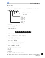
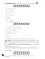
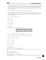
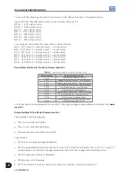
9.1.3 DeviceNet
The DeviceNet communication is used for industrial automation, mainly for the control of valves, sensors, input/
output units and automation equipment. The DeviceNet communication link is based on a communication protocol
“broadcast oriented”, the Controller Area Network (CAN). The physical medium of the DeviceNet network consists
of a shielded cable comprising a twisted pair and two wires for the external power supply. The baud rate can be
set to 125 kbits/s, 250 kbits/s or 500 kbits/s.
Figure 9.7 on page 9-5
shows a general view of a DeviceNet
network.
Controller
Other
devices
Device
configuration
Input/Output
devices
Motor
starter
DeviceNet
Sensor
Motor
controller
Push
button
cluster
Bar code
scanner
Drive
Figure 9.7:
DeviceNet network
Inverter user Fieldbus connector.
5-way plug-in connector with screw terminal, pin assignment according to
Table 9.4 on page 9-5
.
Table 9.4:
DeviceNet terminal block pinout
Terminal
Description
Color
1
V-
Black
2
CAN_L
Blue
3
Shield
-
4
CAN_H
White
5
V+
Red
Summary of Contents for MVW3000 A0040 V023
Page 2: ......
Page 4: ......
Page 5: ...User s Manual Series MVW3000 Language English Document 10004823674 00 Publication Date 03 2017...
Page 6: ...Summary of Reviews Version Review Description R00 First edition...
Page 12: ...1 4 MVW3000 1 Safety Notices...
Page 58: ...6 18 MVW3000 6 Installation Connection and Energization...


