


9-12 | MVW3000
9
Communication Networks
9-12 | MVW3000
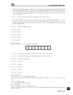
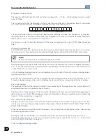
Example: Assuming that no digital output has been programmed for Fieldbus, then if the word 11h is written in
the position 3, the inverter will respond indicating A127 in the Status Word. To remove this indication from the
Status Word it is necessary:
1. To write zero in the position 3 (because no DO has been programmed for Fieldbus).
2. To change the Control Word variable so that the A127 indication be removed from the Status Word.
The removal of the listed errors from the Status Word can also be achieved by writing the 999 code in the position
5 of the variables written in the inverter. Except for A127 (
“b”
and
“a”
cases), whose reset occurs only through the
writing in the Control Word, as exemplified above..
NOTE!
The alarms A0124, A0125, A0126 and A0127 do not cause any change in the inverter operation status.
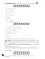
HMI Indications:
A0129 - Inactive Fieldbus onnection
This indication occurs when the physical connection from the inverter to the master is interrupted. The action that
the inverter will take when A0129 is detected is programmed at P0313. The A0129 indication is removed from the
display when the HMI
key is pressed.
E30 - Inactive Fieldbus board.
This indication will appear when:
1. P0309 is programmed different from Inactive, without the existence of the respective board mounted on the
MVC4 board XC140 connector, or
2. The Fieldbus board exists but it is defective, or
3. The board exists; however, the model programmed in P0309 does not match the used board model.
The action that the inverter will take when A0130 is detected is programmed at P0313. The E30 indication is
removed from the display when the HMI
key is pressed.
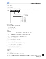
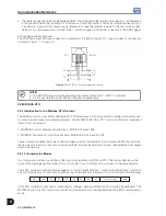
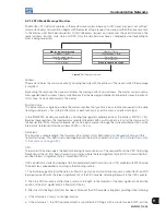
9.1.6.4 MVW3000 Variable Addressing at the Fieldbus Devices
The variables are arranged in the Fieldbus device memory from 00h on, for both writing and reading. What deals
with the address differences is the protocol itself, and the communication board. The manner the variables are
arranged in each address of the Fieldbus device memory depends on the equipment that is being used as
master. In an A PLC, for instance, the variables are arranged High and Low, whereas in a B PLC the variables are
arranged Low and High.
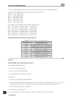
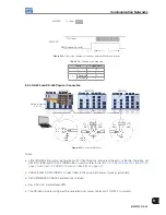
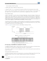
9.2 WEGBUS SERIAL
The basic purpose of the serial communication is the physical connection of the inverters in an equipment
network configured in the following form:
Master
PC, PLC, etc.
Slave 1
(Inverter)
Slave 2
(Inverter)
Slave n
(Inverter)
n ≤ 30
Figure 9.10:
Serial configuration
Summary of Contents for MVW3000 A0040 V023
Page 2: ......
Page 4: ......
Page 5: ...User s Manual Series MVW3000 Language English Document 10004823674 00 Publication Date 03 2017...
Page 6: ...Summary of Reviews Version Review Description R00 First edition...
Page 12: ...1 4 MVW3000 1 Safety Notices...
Page 58: ...6 18 MVW3000 6 Installation Connection and Energization...


