MVW3000 | 9-25
9
Communication Networks
MVW3000 | 9-25
9.3.1.2 RTU Mode Message Structure
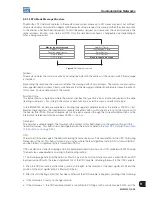
The Modbus-RTU network operates in the master-slave system, where up to 247 slaves may exist, but with just
one master. Every communication begins with the master doing a request to a slave, and then the slave responds
to the master what had been requested. In both telegrams (request and response), the used structure is the
same: address, function code, data and CRC. Only the data field may have a changeable size, depending on
what is being requested.
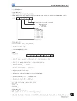
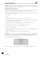
Master request message
Address (1 byte)
Function code (1 byte)
Data (n bytes)
CRC (2 bytes)
Address (1 byte)
Function code (1 byte)
Data (n bytes)
CRC (2 bytes)
Slave response message
Figure 9.15:
Telegram structure
Address:
The master initiates the communication by sending one byte with the address of the slave to which the message
is destined.
By sending the response, the slave also initiates the message with its own address. The master can also send a
message destined to address 0 (zero), which means that the message is intended to all network slaves (broadcast).
In this case, no slave will answer to the master.
Function Code:
This field contains a single byte, where the master specifies the type of service or function requested to the slave
(reading, writing, etc.). According to the protocol, each function is used to access a specific data type.
In the MVW3000 all data are available as holding type registers (referenced from the address 40000 or ’4x’).
Besides these registers, the inverter status (enabled/disabled, with or without error, etc.) and the command for
the inverter (Start/Stop, Forward/Reverse, etc.) can be also accessed through the coil read/write functions, or the
internal bits (referenced from the address 00000 or ‘0x’ on).
Data Field:
This field has a variable length. The format and the content of this field depend on the used function and the
transmitted values. This field is described together with the functions (refer to the
Item 9.3.3 Detailed Description
of the Functions on page 9-30
).
CRC:
The last part of the message is the field for checking transmission errors. The used method is the CRC-16 (Cycling
Redundancy Check). This field is formed by two bytes, where the least significant byte (CRC-) is transmitted first,
and then the most significant byte is transmitted (CRC+).
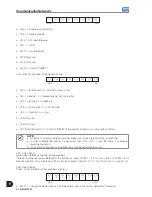
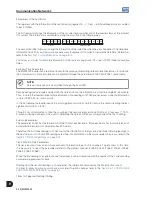
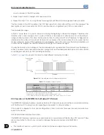
CRC calculation is started by loading a 16-bit variable (mentioned from now on as CRC variable) with FFFFh value.
The next steps are executed according to the following routine:
1. The first message byte (Only the data bits. Start bit, parity bit and stop bit are not used) is submitted to an XOR
logic (exclusive OR) with the 8 least significant bits of the CRC variable, returning the result to the CRC variable.
2. Then the CRC variable is shifted one position to the right, in the direction of the least significant bit and the
position of the most significant bit is filled with 0 (zero).
3. After this shift, the flag bit (bit that has been shifted out the CRC variable) is analyzed, resulting in the following:
If the bit value is 0 (zero), no change is made.
If the bit value is 1, the CRC variable content is submitted to XOR logic with a constant value A001h, and the
Summary of Contents for MVW3000 A0040 V023
Page 2: ......
Page 4: ......
Page 5: ...User s Manual Series MVW3000 Language English Document 10004823674 00 Publication Date 03 2017...
Page 6: ...Summary of Reviews Version Review Description R00 First edition...
Page 12: ...1 4 MVW3000 1 Safety Notices...
Page 58: ...6 18 MVW3000 6 Installation Connection and Energization...


