


3-4 | MVW3000
3
Product Characteristics
R
S
T
F1
F2
D1
D3
D5
D2
D4
D6
R1
R2
C1
Ga
te
d
riv
er
By
pas
s
Ga
te
d
riv
er
FA
NE
Measurement
Supply
Fiber optic
Local control
R
T
S
N
P FA NE
24 V
15 V
5 V
GND
N
TC
1
G
ND
S
1n
, S2
n
15
v
XC
3
15
v
G
ND
N
TC
2
S
1f, S2
f
Tx R
x
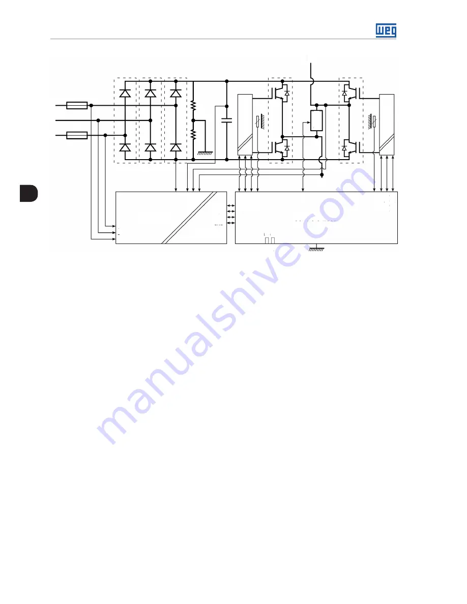
Figure 3.4:
Basic diagram of a power cell
IGBT (Insulated Bipolar Gate Transistor) controlled semiconductor devices are used to implant the inverter bridge
in H; thus, each power cell has four IGBTs in the configuration shown above. During operation, the voltage
between FA and NE output terminals has three possible voltage levels. Considering that the DC link voltage of
each cell is VDC and that only two IGBTs can be operating simultaneously (due to short circuit protection), when
S1f and S2n are operating, the voltage between FA and NE will be + VDC, whereas if S1n and S2f start operating,
the voltage between FA and NE will be –VDC. If S1n and S1f or S2n and S2f are turned on, the voltage, in both
cases, will be equal the zero.
To protect the modules, two fuses F1 and F2 are connected to the input phases R and T, as shown in
Figure 3.1
on page 3-1
. In case a module presents some fault, the bypass system, when available, will be responsible for
circumventing the fault, removing it from the series and enabling the operation to continue.
When that occurs, control strategies will be applied so that the load remains operating. Further information can
be found in
Chapter 8 SPECIAL FUNCTIONS on page 8-1,
in
Section 8.3 CELL BYPASS on page 8-5
.
Each power cell has one local control module. This module communicates with the main control module by
means of an optical-fiber interface, necessary to obtain, in addition to the insulation degree required for the
communication, noise immunity, greater robustness and reliability, characteristics necessary for the application.
The local control makes acquisitions and monitors relevant magnitudes for the cell operation.
Some of the monitored magnitudes are the line voltages of the power cell, temperature of the diode modules and
IGBTs, voltage of the DC link capacitors, voltage of the cell power supplies, among others.
The local control is also responsible for local activations, such as the switching of the IGBTs and the trigger of
the bypass system. In case the cell presents readings out of the expected operation standards, for example,
temperatures close to damaging the semiconductors, overvoltage on the DC link, or other faults predicted by
the control, the bypass system may be activated for protection against a possible cell failure or for removing an
already damaged cell from operation.
Summary of Contents for MVW3000 A0040 V023
Page 2: ......
Page 4: ......
Page 5: ...User s Manual Series MVW3000 Language English Document 10004823674 00 Publication Date 03 2017...
Page 6: ...Summary of Reviews Version Review Description R00 First edition...
Page 12: ...1 4 MVW3000 1 Safety Notices...
Page 58: ...6 18 MVW3000 6 Installation Connection and Energization...


