MVW3000 | 9-29
9
Communication Networks
MVW3000 | 9-29
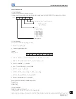
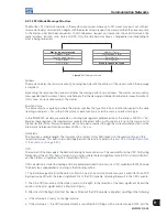
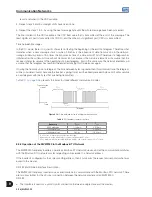
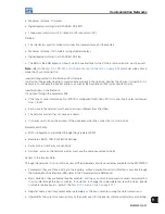
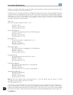
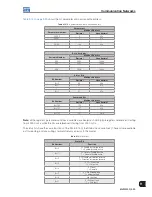
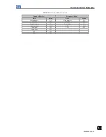
Table 9.12 on page 9-29
shows the bit, parameter and basic variable address:
Table 9.12:
Bit, parameter and basic variable address
Parameters
Parameter Number
Modbus Address
Decimal
Hexadecimal
P0000
0
00h
P0001
1
01h
...
...
...
P0100
100
64h
...
...
...
Basic Variables
Variable Number
Modbus Address
Decimal
Hexadecimal
V00
5000
1388h
V01
5001
1389h
...
...
...
V08
5008
1390h
Status Bits
Bit Number
Modbus Address
Decimal
Hexadecimal
Bit 0
00
00h
Bit 1
01
01h
...
...
...
Bit 7
07
07h
Command Bits
Bit Number
Modbus Address
Decimal
Hexadecimal
Bit 100
100
64h
Bit 101
101
65h
...
...
...
Bit 107
107
6Bh
Note:
all the registers (parameters and basic variables) are treated as holding type registers, referenced starting
from 40000 or 4x, while the bits are referenced starting from 0000 or 0x.
The status bits have the same functions of the bits 8 to 15 of the Status (basic variable 2). These bits are available
just for reading, and any writing command returns an error to the master.
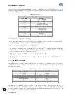
Table 9.13:
Status Bit
Status Bit
Bit Number
Function
Bit 0
0 = Enable by ramp inactive
1 = Enable by ramp active
Bit 1
0 = General Enable inactive
1 = General Enable active
Bit 2
0 = Direction of rotation reverse
1 = Direction of rotation forward
Bit 3
0 = JOG inactive
1 = JOG active
Bit 4
0 = Local
1 = Remote
Bit 5
0 = No undervoltage
1 = Undervoltage
Bit 6
No function
Bit 7
0 = Without fault
1 = With fault
Summary of Contents for MVW3000 A0040 V023
Page 2: ......
Page 4: ......
Page 5: ...User s Manual Series MVW3000 Language English Document 10004823674 00 Publication Date 03 2017...
Page 6: ...Summary of Reviews Version Review Description R00 First edition...
Page 12: ...1 4 MVW3000 1 Safety Notices...
Page 58: ...6 18 MVW3000 6 Installation Connection and Energization...


