


MVW3000 | 7-13
7
MVW3000 | 7-13
Optional Accessories and Boards
XC9
XC10
XC7
XC
4
XC3
EE
XC5
XC11
XC22
XC
21
C13
1 2
1
2
2
1
1
2
3
1
1
1
2
3
4
5
1
1
5
6
2
16
B
1
B
1
B
1
B
2
B
2
B
2
NA
NA
NA
K1
K2
K3
C
C
C
30
1
15
6
6
9
9
5
5
26
W7
39
51
75
76
50
24
25
1
1 2
33
34
31
32
33
34
DG
N
D
DND
C
D6
D4
D1
W
11
XC1
XC
2
XC82
XC81
XC
6
W12
H7
2
1
1
1
1 2
S1 NO
1
XC
17
1
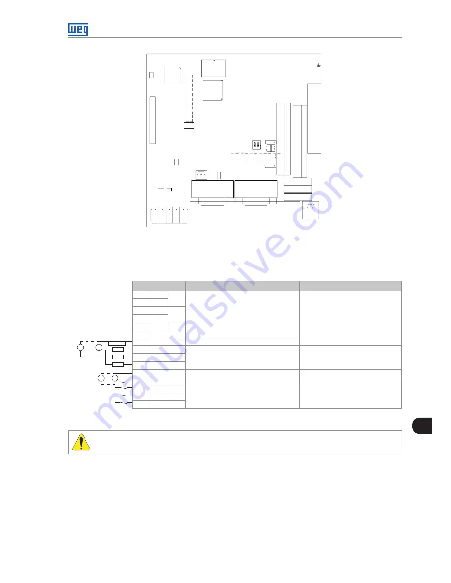
Figure 7.13:
PLC2 connectors
The connectors and their terminals function are described below.
XC21 Connector: Relay Outputs and Digital Inputs
XC21 Connector
Function
Specification
1
C
DO1
Digital relay outputs
Contact capacity:
3 A
250 Vac
2
N
3
C
DO2
4
NA
5
C
DO3
6
NA
7
COM DO
Reference for digital outputs DO4, DO5, DO6
-
8
DO4
Bidirectional opto-isolated
digital outputs
Maximum voltage: 48 Vdc
Current capacity: 500 mA
9
DO5
10
DO6
11
COM DI
Reference for digital inputs DI1 to DI9
-
12
DI9
Bidirectional
isolated digital Inputs
Input voltage: (15 to 30) Vdc
Input current: 11 mA @ 24 Vdc
13
DI8
14
DI7
15
DI6
+
-
+
-
+
-
+
-
Load
(*)
(*)
Figure 7.14:
Description of XC21 connector
ATTENTION!
(*)
External power supply.
Summary of Contents for MVW3000 A0040 V023
Page 2: ......
Page 4: ......
Page 5: ...User s Manual Series MVW3000 Language English Document 10004823674 00 Publication Date 03 2017...
Page 6: ...Summary of Reviews Version Review Description R00 First edition...
Page 12: ...1 4 MVW3000 1 Safety Notices...
Page 58: ...6 18 MVW3000 6 Installation Connection and Energization...


