7-14 | MVW3000
7
7-14 | MVW3000
7
Optional Accessories and Boards
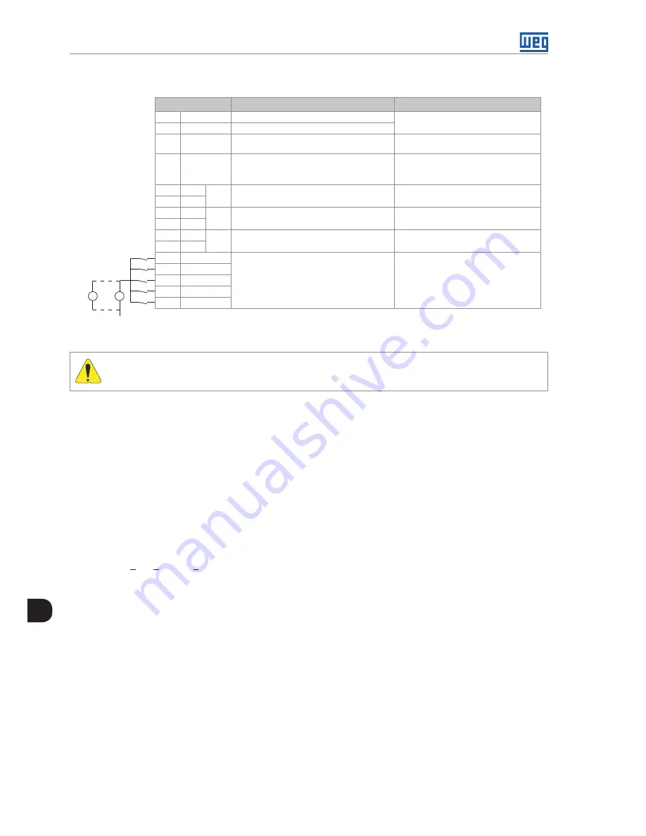
XC22 Connector: Transistor Outputs and Digital Inputs
XC22 Connector
Function
Specificationss
16
PTC1
Motor thermistor input
Actuation: 3.9 k Release: 1.6 k
Minimum resistance: 100 Ω
17
PTC2
PTC
18
GND ENC
Reference for the power supply of the
encoder input
-
19
+ ENC
Encoder input
power supply
Controlled 5 Vdc or (8 to 24) Vdc
Current consumption: 50 mA +
Encoders current
(**)
20
-
AO2
Analog output 2
(-10 to +10) Vdc or (0 to 20) mA
12 Bits
21
+
22
-
AO1
Analog output 1
(-10 to +10) Vdc or (0 to 20) mA
12 Bits
23
+
24
-
AI1
Differential analog
input 1
(-10 to +10) Vdc or (-20 to 20) mA
14 Bits
25
+
26
DI1
Bidirectional, isolated
digital inputs
Input voltage: (15 to 30) Vdc
Input current: 11 mA @ 24 Vdc
27
DI2
28
DI3
29
DI4
30
DI5
+
-
+
-
(*)
COM DI
Figure 7.15:
Description of XC22 connector
ATTENTION!
(*)
External Power supply.
(**)
For current, the S1 switch must be set ON.
7.3 INCREMENTAL ENCODER
Applications that require more speed or positioning accuracy, a speed feedback of the motor shaft by means of
incremental encoder is required. The connection to the inverter is made through the XC9 connector (DB9) on the
EBA function expansion board, or XC9 on EBB, or XC10 on EBC.
7.3.1 EBA/EBB Boards
When the EBA or EBB board is used, the selected encoder should have the following characteristics:
Power supply voltage: 12 Vdc, less than 200 mA current consumption.
2 quadrature channels (90º) + zero pulse with complementary outputs (differential):
Signals A, A, B, B, Z and Z.
"Linedriver" or "Push-Pull" output circuit type (12 V level).
Electronic circuit isolated from the encoder frame.
Recommended number of pulses per revolution: 1024 ppr.
Follow the recommendations bellow when mounting the encoder on the motor:
Couple the encoder directly to the motor shaft (use a flexible coupling without torsional flexibility).
Both the shaft and the metallic frame of the encoder must be electrically isolated from the motor (3 mm (0.119
in) minimum distance).
Use high quality flexible couplings to prevent mechanical oscillation or backlash.
The electrical connections must be made with shielded cable, maintaining a minimum distance of about 25 cm
(10 in) from other wires (power, control cables, etc.). If possible, install the encoder cable in a metallic conduit.
Summary of Contents for MVW3000 A0040 V023
Page 2: ......
Page 4: ......
Page 5: ...User s Manual Series MVW3000 Language English Document 10004823674 00 Publication Date 03 2017...
Page 6: ...Summary of Reviews Version Review Description R00 First edition...
Page 12: ...1 4 MVW3000 1 Safety Notices...
Page 58: ...6 18 MVW3000 6 Installation Connection and Energization...


