


MVW3000 | 9-9
9
Communication Networks
MVW3000 | 9-9
There are some parameters whose representation on the LED display can suppress the decimal position when
the values are higher than 99.9. These parameters are P0100, P0101, P0102, P0103, P0156, P0157, P0158,
P0169 (for P0202 < 3), P0290 and P0401.
Example: Indication on the LED display: 130.
Indication on the LCD : 130.0, Fieldbus reading is: 1300.
The reading of parameter P0006 via Fieldbus has the meaning presented in the detailed description of the
parameters, refer to the programming manual available for download on:
www.weg.net
.
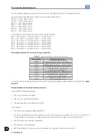
5. Torque current:
This position indicates P009 parameter contents, without the decimal point. A low pass filter with a time constant
of 0.5 s filters this variable.
6. Motor current:
This position indicates P003 parameter contents, without the decimal point. A low pass filter with a time constant
of 0.3 s filters this variable.
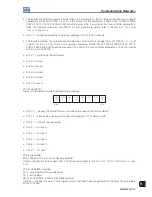
9.1.6.2 Variables Written in Inverter
The variables are written in the following order:
1. Control word.
2. Motor speed reference, for the option P309 = 1 or 4 (2I/O) - it writes in 1 and 2.
3. Status of the digital outputs.
4. Number of the parameters to be read, for the option P0309 = 2 or 5 (4I/O) - it writes in 1, 2, 3 and 4.
5. Number of the parameter to be changed.
6. Content of the parameter to be changed, selected in the previous position, for the option P0309 = 3 or 6 (6I/O)
- it writes in 1, 2, 3, 4, 5 and 6.
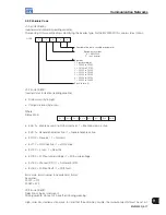
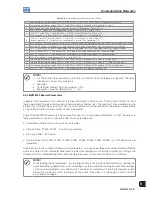
1. Control word (C.L.):
The control word is composed by a total of 16 bits, 8 high order bits and 8 low order bits. It has the following
construction:
High-order bits - they select the functions to be controlled, when the correspondent bits are set to 1.
CL.15 - Inverter fault reset.
CL.14 - Without function.
CL.13 - To save the changes of parameters P0169/P0170 in the EEPROM.
CL.12 - Local/Remote command.
CL.11 - Jog command.
CL.10 - Forward/Reverse.
CL.09 - General Enabling.
CL.08 - Start/Stop.
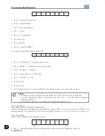
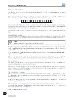
Low-order bits - they determine the activation of the functions selected in the high-order bits,
CL.7 - Inverter fault reset: every time it changes from 0 to 1 it causes an inverter reset, except for the errors (except
A0124, A0125, A0126 and A0127);
CL.6 - No function.
CL.5 - To save P169/P170 in the EEPROM: 0 = to save, 1 = not to save.
CL.4 - Local/Remote command: 0 = Local, 1 = Remote.
CL.3 - Jog command: 0 = Inactive, 1 = Active.
CL.2 - Forward/Reverse: 0 = Reverse, 1 = Forward.
CL.1 - General enabling: 0 = Disabled, 1 = Enabled.
CL.0 - Start/Stop: 0 = Stop, 1 = Start.
Summary of Contents for MVW3000 A0040 V023
Page 2: ......
Page 4: ......
Page 5: ...User s Manual Series MVW3000 Language English Document 10004823674 00 Publication Date 03 2017...
Page 6: ...Summary of Reviews Version Review Description R00 First edition...
Page 12: ...1 4 MVW3000 1 Safety Notices...
Page 58: ...6 18 MVW3000 6 Installation Connection and Energization...


