

9-30 | MVW3000
9
Communication Networks
9-30 | MVW3000
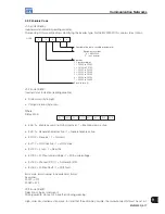
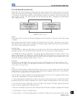
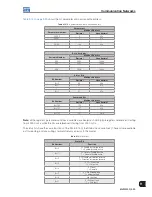
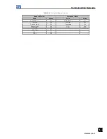
The command bits are available for reading and writing, and have the same function of the bits 0 to 7 of the
Control Word (basic variable 3), without the necessity, however, of the mask use. Writing in the basic variable 3
has influence in the state of these bits.
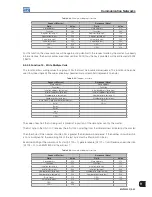
Table 9.14:
Command Bits
Command Bit
Bit Number
Function
Bit 100
0 = Disable ramp (Stop)
1 = Enable ramp (Run)
Bit 101
0 = General Disable
1 = General Enable
Bit 102
0 = Direction of rotation reverse
1 = Direction of rotation forward
Bit 103
0 = Deactivates JOG
1 = Activates JOG
Bit 104
0 = Go to Local mode
1 = Go to Remote mode
Bit 105
No function
Bit 106
No function
Bit 107
0 = Does not reset the inverter
1 = Resets the inverter
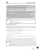
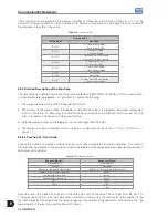
9.3.3 Detailed Description of the Functions
This item presents a detailed description of functions available at the MVW3000 for Modbus-RTU communication.
In order to elaborate the telegrams, it is important to observe the following:
The values are always transmitted in hexadecimal format.
The address of one piece of data, the number of data and the value of the registers, are always represented
in 16 bits. Therefore, it is necessary to transmit those fields using two bytes (high and low). To access bits, the
form to represent a bit depends on the used function.
Both the request and response telegrams, cannot be longer than 128 bytes.
The resolution of each parameter or basic variable is as described in the
Item 9.2.1 Protocol Definitions on
page 9-15
.
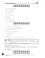
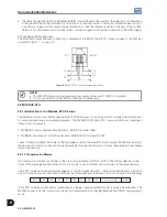
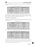
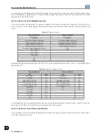
9.3.3.1 Function 01 - Read Coils
It reads the contents of a group of internal bits that must necessarily be in a numerical sequence. This function
has the following structure for the request and response telegrams (the values are always hexadecimal, and each
field represents one byte:
Table 9.15:
Telegram structure
Request (Master)
Response (Slave)
Slave address
Slave address
Function
Function
Address of the initial bit (byte high)
Field Byte Count (number of data bytes)
Address of the initial bit (byte low)
Byte 1
Number of bits (byte high)
Byte 2
Number of bits (byte low)
Byte 3
CRC-
etc a
CRC+
CRC-
-
CRC+
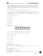
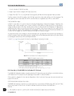
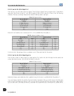
Each response bit is placed at a position of the data bytes sent by the slave. The first byte, from the bits 0 to
7, receives the first 8 bits from the initial address indicated by the master. The other bytes (if the number of the
read bits is greater than 8) remain in the same sequence. If the number of the read bits is not a multiple of 8, the
remaining bits of the last byte must be filled with 0 (zero).
Summary of Contents for MVW3000 A0040 V023
Page 2: ......
Page 4: ......
Page 5: ...User s Manual Series MVW3000 Language English Document 10004823674 00 Publication Date 03 2017...
Page 6: ...Summary of Reviews Version Review Description R00 First edition...
Page 12: ...1 4 MVW3000 1 Safety Notices...
Page 58: ...6 18 MVW3000 6 Installation Connection and Energization...


