9-6 | MVW3000
9
Communication Networks
9-6 | MVW3000
Line Termination
The initial and the end points of the network must present the characteristic impedance, in order to prevent
reflections. Thus a 121 Ω/0.5 W resistor must be connected between the terminals 2 and 4 of the Fieldbus
terminal block.
Baudrate/Node Address
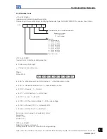
There are three different baudrates for DeviceNet: 125 kbits/s, 250 kbits/s and 500 kbits/s. Choose the baudrate
by setting the DIP switches on the electronic board, before the network configuration. The node address is
selected through the six DIP switches on the electronic board, permitting addressing from 0 to 63.
Baudrate
[bits/s]
DIP Switches 1
and 2
125 k
00
250 k
01
500 k
10
Reserved
11
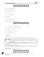
Address
DIP3 to DIP8
0
000000
1
000001
2
000010
...
...
61
111101
62
111110
63
111111
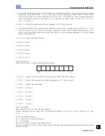
Address
Baudrate
ON
1
1
0
2 3 4 5 6 7 8
Figure 9.8:
DeviceNet baudrate and node address configuration
Configuration File (EDS File)
Each element of a DeviceNet network is associated to an EDS file, which has all information about the element.
This file supplied with the product is used by the network configuration program.
By means of the parameter P0309 it is possible to select 2, 4 or 6 input/output words, when P0309 is programmed
4, 5 or 6, respectively (refer to the
Item 9.1.6 Fieldbus Application/MVW3000 Related Parameters on page 9-7
).
Define in the network configuration program the number of exchanged words, according to the number selected
at the parameter P0309. The type of connection used for data exchange must be “Polled I/O”.
NOTE!
The PLC (master) must be programmed for Polled I/O connection.
Signaling
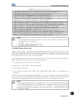
The electronic board has a bicolor LED indicating the status of the Fieldbus according to the
Table 9.2 on page
9-4
.
NOTE!
The red signalizations may indicate hardware problems on the electronic board. Its reset is performed
by cycling the power of the inverter. If the problem persists, replace the electronic board.
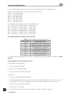
The board also has other four LEDs grouped at the right bottom corner, indicating the Fieldbus network status
according to
Figure 9.9 on page 9-6
and
Table 9.5 on page 9-7
below.
Reserved
Network status
Module
network status
Reserved
Figure 9.9:
LEDs indicating the status of the DeviceNet network
Summary of Contents for MVW3000 A0040 V023
Page 2: ......
Page 4: ......
Page 5: ...User s Manual Series MVW3000 Language English Document 10004823674 00 Publication Date 03 2017...
Page 6: ...Summary of Reviews Version Review Description R00 First edition...
Page 12: ...1 4 MVW3000 1 Safety Notices...
Page 58: ...6 18 MVW3000 6 Installation Connection and Energization...


