Doc. P/N: WSP-009-005
Version: V1.5
Issue Date: October 2013
www.wassp.com
Page 39 of 73
Installation Manual
10.1 Dockside Tests
The first part of the commissioning procedures requires a number of
dockside tests
to confirm
that the WASSP system is installed and operating correctly, before actually taking to sea.
10.1.1 Commissioning Step 1: Ship Measurements
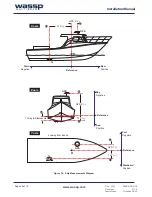
Take measurements on the vessel between the vessel’s reference point, the GPS antenna, and
the transducer’s receiver face. These measurements must be as accurate as possible. See
“Figure 34. Ship Measurements Diagram” on page 40. The accuracy of these measurements
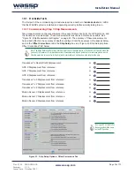
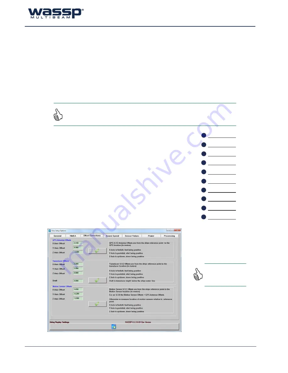
has a direct effect on the accuracy of depth soundings. Enter these values in the spaces below,
and on the
Offset Corrections
tab in the
Ship Setup
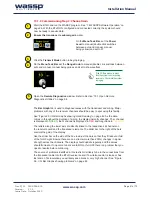
box, see “Figure 33. Ship Setup Options -
Offset Corrections Tab” below.
Transducer Tx Depth (Draft) Displacement:
m
GPS X Displacement from reference:
m
GPS
Y
Displacement
from
reference:
m
GPS Z Displacement from reference:
m
Transducer Tx X Displacement from reference:
m
Transducer Tx Y Displacement from reference:
m
Transducer Tx Z Displacement from reference:
m
Motion Sensor X Displacement from reference:
m
Motion Sensor Y Displacement from reference:
m
Motion Sensor Z Displacement from reference:
m
A
B
C
D
E
F
G
H
I
J
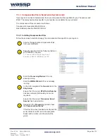
Figure 33. Ship Setup Options - Offset Corrections Tab
If using an SC30, the Motion
Sensor position is the same
as the GPS position.
Note: The Ships Reference Point is an Arbitrary point close to the ships centre of Pitch and Roll. It pays to make this
point easy to measure to for improved accuracy of measurements. A good guideline for a reference point is a point
near the water line in the centre of the ship (port to starboard) and half way down the length of the ship.

