Doc. P/N:
WSP-009-005
Version: V1.5
Issue Date:
October 2013
www.wassp.com
Page 22 of 73
Installation Manual
6.2.3.1 Transmitter Cable Socket Assembly
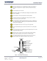
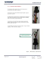
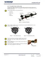
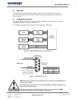
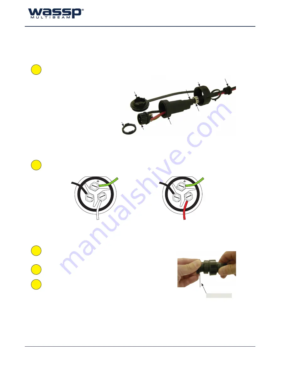
If the transmitter cable socket needs to be disassembled, use the locking ring tightening tool
supplied with the BTxR to loosen the locking ring. To assemble the 3-pin sealed plug on the end
of the transmitter cable:
Push the following parts over the transmitter wires:
•
Gland Nut.
•
Gland Cage.
•
Gland.
•
Main Body.
Gland Cage
Gland
Gland Nut
Locking Cap
Main Body
Socket
Locking Ring
Locking Ring
Tightening Tool
E
L
N
RED
GREEN
BLACK
Push the socket into the main body, rotating to make sure that
the flat edge on the socket is aligned with the flat edge on the
main body.
Using the tightening tool, screw the locking ring into the front of
the socket until tight.
Push the gland, gland cage, and gland nut into the main body as
far as it will go and tighten the nut securely.
Tightening Tool
E
L
N
WHITE
GREEN
BLACK
Figure 16. Cable Socket Assembly
2
3
4
1
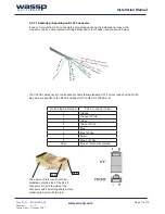
Attach the RED or WHITE wire to L, the BLACK wire to N, and the GREEN wire to E on the
socket and tighten all three screws.
Figure 17. Later cable colour code
Figure 18. Early cable colour code
5

