Doc. P/N: WSP-009-005
Version: V1.5
Issue Date: October 2013
www.wassp.com
Page 15 of 73
Installation Manual
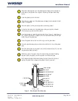
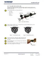
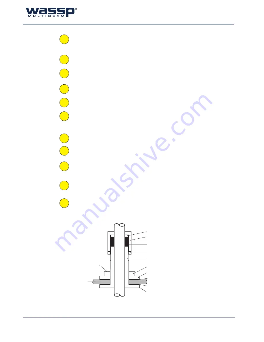
TRANSDUCER
CABLE
GLAND NUT
STEEL WASHER
GLAND PACKING RING
GLAND PIPE
HULL PLATE
GLAND PIPE FLANGE
LOCK SCREW
Cut away of gland
GLAND LOCK NUT
LOCK PLATE
GASKET ABOVE HULL
GASKET BELOW HULL
VESSEL HULL
OR
SEA CHEST
COVER
Figure 8. Mounting the Gland Assembly
Place the bottom gasket over the gland pipe and apply marine sealant to
both sides of the gasket. See “Figure 8. Mounting the Gland Assembly”
below.
Push the gland pipe into the hole.
Place the top gasket over the gland pipe and apply marine sealant to both
sides of the gasket.
Place the plate over the gland pipe and onto the top gasket.
Screw the lock plate onto the gland pipe until a good joint is achieved.
Clean away any excess marine sealant.
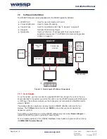
Feed the transducer cable through the gland. See “Figure 9. Gland Assem-
bly - Cable Connectors” on page 16 for a set of steps to feed a RJ-45 type
cable through the gland pipe.
Screw the gland lock nut as far as it can go onto the gland pipe.
Place the gland packing ring over the cable until it sits on top of the gland
pipe.
Place the steel washer and gland nut over the cable and screw the nut onto
the gland pipe firmly by hand.
With the vessel in the water, check for leaks at the gland and if leaking
slightly, tighten the gland nut with a spanner until the leak stops.
With all leaks stopped and while holding the gland nut with a spanner,
tighten the gland lock nut against the gland nut with a spanner.
1
2
3
4
8
5
6
9
11
7
10


