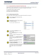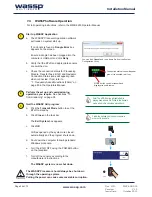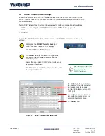
Doc. P/N: WSP-009-005
Version: V1.5
Issue Date: October 2013
www.wassp.com
Page 27 of 73
Installation Manual
GPS
Opto
Coupler
NMEA
RS232
Heading
Sensor
Motion
Sensor
Opto
Coupler
NMEA
RS232
RS232
WASSP
Processor
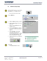
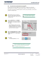
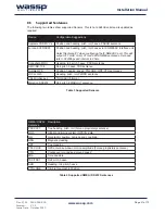
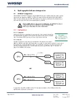
8. Sensors
The WASSP system requires position, heading, attitude, heave, speed and time information in
order to be fully functional. The overall performance will be directly affected by the quality of the
sensors chosen.
8.1 NMEA Interconnection
The WASSP system will extract the required data from NMEA input format sentences as well as
proprietary RS232 from supported motion sensors.
For full details on installation and connection, refer to Equipment Manuals.
NMEA sentences need to be converted from the current loop to the RS232 that is
used by the computer.
If the data sources (talkers) do not have the capability of doing this themselves, a
data converter must be used.
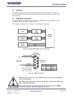
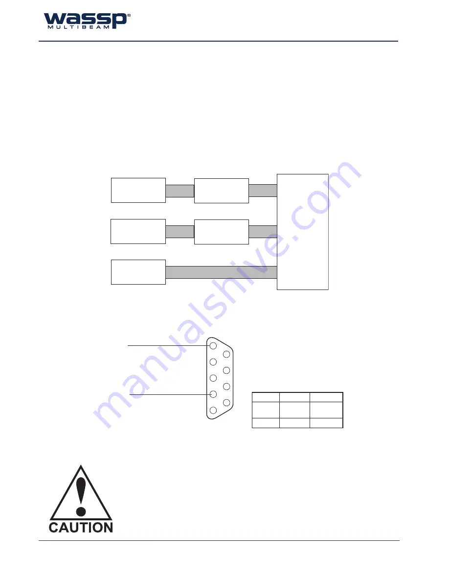
Data cables should be run from existing sensors on the vessel to the WASSP
Processor serial ports using 9-pin female D connectors.
Figure 20. Example NMEA /RS232 Sensor Connections
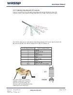
Figure 21. NMEA Pin in Pin Out
Pin No.
Colour
Function
2
BROWN
Data from
sensor
5
YELLOW
Ground
Viewed from the
solder side.
9-pin D Type
Female Connector
1
2
3
4
5
6
7
8
9
NMEA Cable
Tx-
Tx+
Data from sensor
GND
BROWN
YELLOW or GREEN
Note: the supplied cable may
have yellow or white conductor
for the Tx+ data connection

