Doc. P/N: WSP-009-005
Version: V1.5
Issue Date: October 2013
www.wassp.com
Page 17 of 73
Installation Manual
RJ-45 Plug Pin Number
CAT 5 conductor colour
1
Orange
2
Orange / White
3
Green
4
Green / White
5
Blue
6
Blue / White
7
Brown
8
Brown / White
Case
Screen / drain wire (solder)
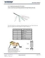
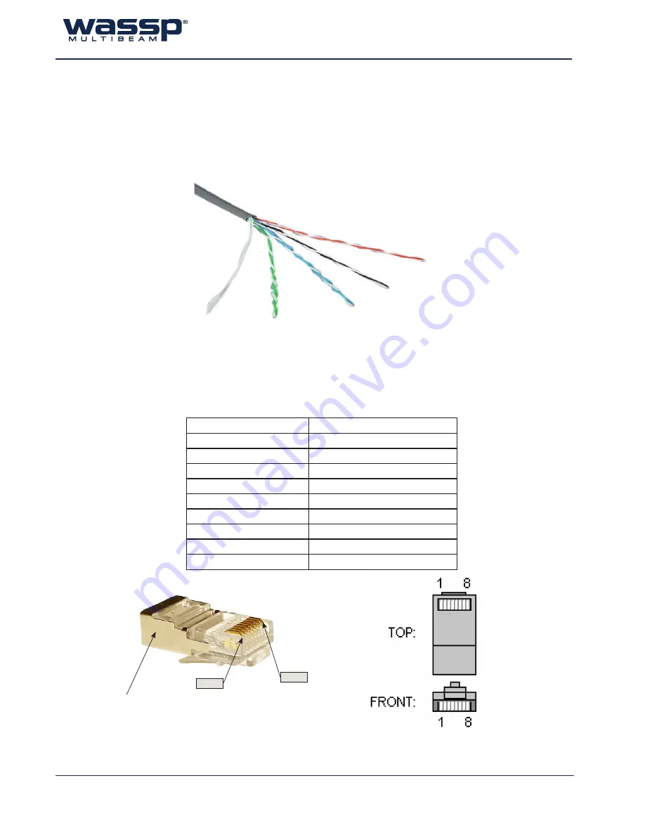
The CAT5E cables used in the transducer cable follow standard CAT5 colour codes but the RJ-45
plug wiring is specific to the BTxR and does NOT conform to T568A or B:
Pin #8
Pin #1
Screen / dr
ain wir
e
Blue and
Blue
Wh
ite
Brow
n an
d Bro
wn / W
hite
Green and Green /
Whit
e
Orange and
Orange /
White
5.5.2.1 Replacing / Repairing an RJ-45 Connector
If one or more of the RJ-45 connectors gets damaged during the installation process, the
connector can be easily replaced. Wiring details and colour codes used are shown below.
The screen / drain wire should be
soldered onto the side of the RJ-45
connector. Scratch the side of the
connector with something sharp before
soldering to assist with the join.

