59
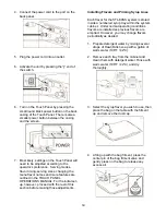
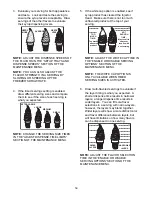
2. Remove the 9-hole gasket from the end of
the 9-Tube Assembly line. Spray the end of
the 9-Tube Assembly, the gasket, and the
end of the lead with sanitizer solution. Allow
these parts to sanitize for at least 5 minutes.
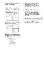
3. Connect the 9-Tube Lead with the 9-Tube
Assembly, with the 9-hole gasket in
between. Align the 9-hole gasket with the
coupler pins of the 9-Tube Lead and place
the gasket against the coupler. Then align
the coupler pins of the two tube assemblies
and connect them.
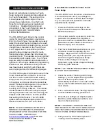
4. Slide the coupler casing over the connection
and screw each coupler nut into each end of
the casing. Tighten the coupler nuts to
secure the connection.
Power Connections and Power Up
The electrical connections for the STL-80SS
are located on the upper back panel of the unit.
Once the cables have been attached and the
unit is turned on, the STL-80SS can remain on
during normal operations from day to day. It
does not need to be turned off unless it is being
serviced or moved, or unless it is not used for a
long period of time.
NOTE:
ELELCTRICAL HAZARD - DO NOT
HANDLE OR OPERATE NEAR WATER.
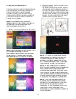
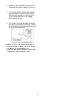
1. Ensure the power-switch is in the “off”
position with the “
○
” end pressed in.
2. Connect the Drive Motor cable to the round
metal port.
3. Connect the ethernet cable to the ethernet
port in the plastic gland. Screw the plastic
cover over the connection and secure the
ethernet gland assembly with the nut.
Summary of Contents for STL-80SS
Page 2: ......
Page 9: ...6 PAGE INTENTIONALLY LEFT BLANK ...
Page 11: ...8 General System Overview Figure 1 ...
Page 13: ...10 Cabinet Continued Figure 2 ...
Page 17: ...14 Syrup Pump and Related Parts Figure 4 ...
Page 19: ...16 Sanitizer Pump and Related Parts Figure 5 ...
Page 23: ...20 Spare Parts Kit Figure 7 ...
Page 24: ...21 PAGE INTENTIONALLY LEFT BLANK ...
Page 36: ...33 PAGE INTENTIONALLY LEFT BLANK ...
Page 50: ...47 PAGE INTENTIONALLY LEFT BLANK ...
Page 73: ......
Page 74: ......

