background image

 53

IP DECT 6000 System Installation & Configuration Guide

A100K10652

After setting up communication between the base station and the 

computer, access the base station by logging into its web interface using 

a standard web browser.

1.  Open a web browser.
2.  In the browser’s 

Address

 bar, enter IP address 

192.168.0.1

, and 

press the 

ENTER

 key.

The Login page is displayed.

When you access the user interface for the first time, you need to log in 

with a user name and password.


)

The default user name of the system is 

admin

 and the default password of the 

system is 

ip6000

. It is strongly recommended to change the password - see 

“Changing System User Name and Password”.

To log in:

1.  In the 

User Name

 field, enter 

admin

.

2.  In the 

Password

 field, enter 

ip6000

.

3.  Click 

OK

.

 
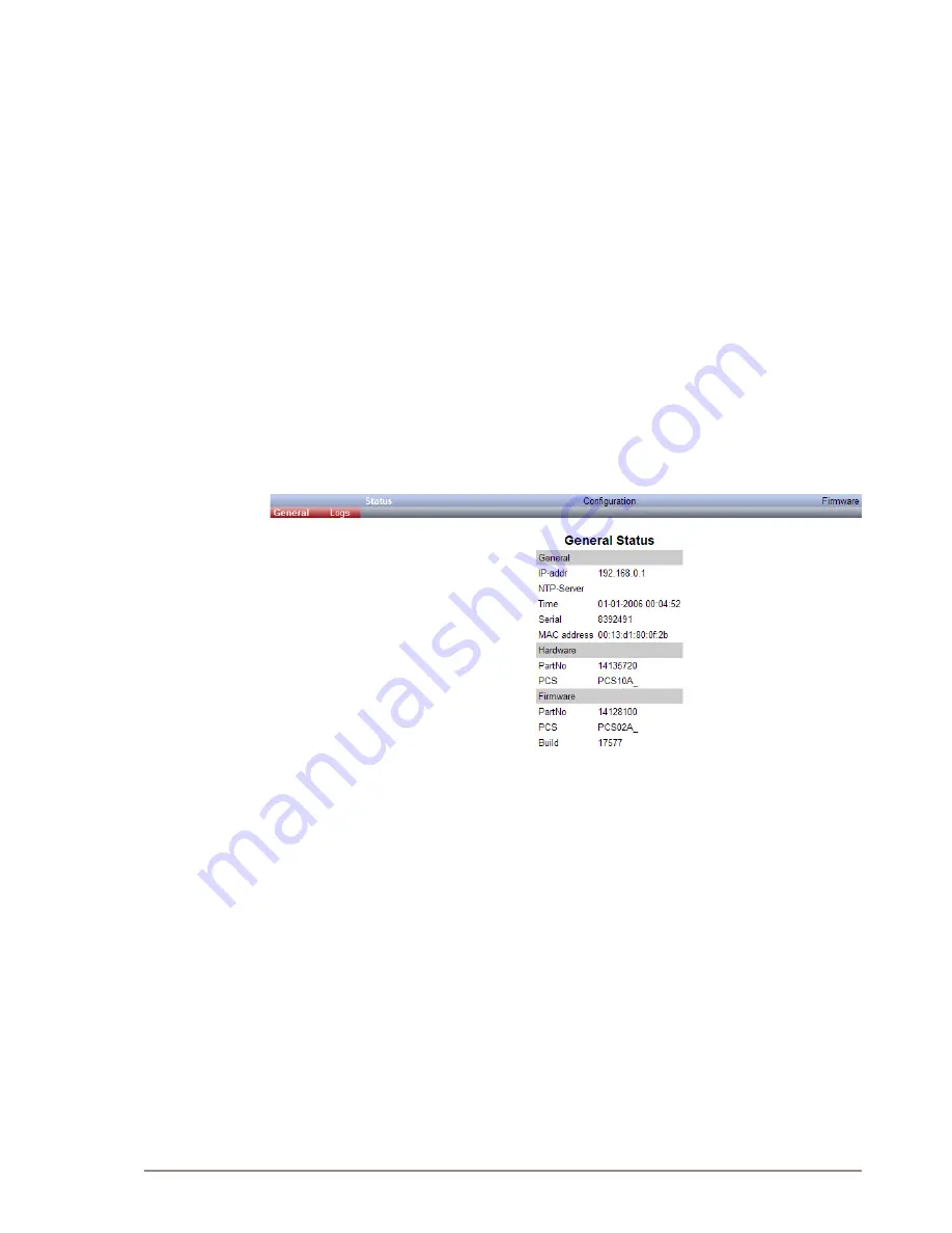
The Base Station 

General Status

 page is displayed.

Summary of Contents for IP DECT 6000

Page 1: ...TECHNICAL MANUAL A100K10652 INSTALLATION CONFIGURATION GUIDE IP DECT 6000 System...

Page 2: ...sing from the information in it No information in this publication should be regarded as a warranty made by Zenitel Norway AS The information in this publication may be revised or changed without noti...

Page 3: ...cement 14 3 2 Deployment of a Server 6000 Multi Cell System 15 3 2 1 Sync over Air 15 3 2 2 Examples of Synchronization Chains 15 3 2 2 1 Sync Chain With One Sync Master Primary Sync Ways 16 3 2 2 2 S...

Page 4: ...t 40 7 3 2 2 Rough Office Handset 40 7 4 Retrieving the Serial Number of the Handset 41 7 4 1 Retrieving Serial Number on EX Handset 41 7 4 2 Retrieving Serial Number on Office Handset 42 8 Configurin...

Page 5: ...rmation 72 12 1 2 2 Logs Information 72 12 1 2 3 Wireless Server Information 74 12 1 3 Reading Statistics 74 12 1 3 1 Wireless Server 74 12 1 3 2 Base Station 75 12 1 3 3 Active Calls 75 12 1 3 4 Abno...

Page 6: ...Figure 15 Base Station Wall Mounting 26 Figure 16 Base Station Ethernet Connector 26 Figure 17 Repeater Programming Kit 29 Figure 18 Removing Back Cover from EX Handset 38 Figure 19 Removing Back Cov...

Page 7: ...under Related Documentation below 1 1 Before You Begin This document assumes the following You have a working knowledge of AlphaCom ACM exchange operations and the exchange is installed and initialize...

Page 8: ...components IP DECT Server 6000 Base Stations Repeaters Administrative Computer Handsets and accessories Alarm Server Figure 1 IP DECT 6000 System Configuration Base Station Repeater DECT Handset Roug...

Page 9: ...SI DECT 1880 1900 MHz referred to as DECT USA DECT 1920 1930 MHz referred to as 1G9 The wireless band used by an IP DECT 6000 System is determined by the base stations and handsets delivered with the...

Page 10: ...the repeater and software downloads to the repeater is called ServiceTool ServiceTool is not used for adjusting the Rough Office Handset The ServiceTool software is available as a download from the S...

Page 11: ...cable solution is used instead Only position base stations and repeaters where the signal is needed The installation area must be clean free of traffic and excess dust dry and well ventilated The inst...

Page 12: ...0 Hz 2 7 4 Maintenance Software This section describes the computer requirements to run the installation and maintenance tools of the handset and repeater 2 7 4 1 Software Requirements Operating Syste...

Page 13: ...onfigure the system on site Handsets To use the handsets you must first install the radio infrastructure e g base stations and repeaters to transmit and receive radio signals to and from the handsets...

Page 14: ...uch as ship cargo rooms it is not to be expected that the standard radio antenna base stations will be able to support handover For deployment on ships the radiating cable solution may be used For eff...

Page 15: ...Cell System 3 2 1 Sync over Air As a user moves from one base station radio coverage area to another the call must be handed over to the next radio unit To create handover between radio units it is ne...

Page 16: ...sync Radio ID 3 2 2 1 Sync Chain With One Sync Master Primary Sync Ways Figure 2 Synchronization Chain The synchronization chain must always overlap with the base station to sync on No 0 is the Sync...

Page 17: ...Primary and secondary sync on No 0 No 11 Primary sync on No 10 and secondary sync on No 21 Figure 5 Synchronization Chain with Secondary Sync Ways No 0 is the Sync Master may be numbered 0 to 255 No...

Page 18: ...nc on No 0 No 11 Primary sync on No 10 and secondary sync on No 21 No 21 Primary sync on No 20 and secondary sync on No 11 No 31 Primary sync on No 30 and secondary sync on No 41 No 41 Primary sync on...

Page 19: ...No 22 and No 23 Only primary sync No 25 Primary sync on No 24 and secondary sync on No 15 No 11 and No 21 Only handover overlap Marked in green Figure 9 Synchronization Chain With Repeaters No 0 is th...

Page 20: ...ce and Components The Server 6000 front cover has a LED located in the middle that indicates the operating status of the unit Figure 10 Server 6000 Front view 4 1 3 Server 6000 LED Indicators 4 1 3 1...

Page 21: ...reset the Server 6000 by pressing the Reset button on the faceplate Figure 11 Server 6000 Faceplate 4 1 4 1 Resetting the Server 6000 Hardware This section contains a description of the different acti...

Page 22: ...unting indoors on a wall The procedure is as follows 1 Mount the Server 6000 on the wall using the anchors and screws provided 2 Connect the power supply cable into the RJ45 plug on the Server 6000 Wh...

Page 23: ...e base station is to provide audio and data communication between the handsets and the Server 6000 The base station supports 11 RF channels for DECT or USA DECT bands The base station is also termed t...

Page 24: ...tion LED Indicators 5 1 4 1 Front Cover The base station front cover has one indicator describing the base station faults and failures The indicator is off when the base station is not powered The LED...

Page 25: ...empty user database and restarts the system Firmware version is not affected 5 2 Mounting Connecting the Base Station The base station is suitable for mounting indoors on a wall Before beginning the...

Page 26: ...RJ45 plug into the Ethernet connector at the bottom of the base station When you place the base station on the screws ensure that the screws do not touch the printed circuit board Figure 16 Base Stati...

Page 27: ...annels It is wireless and does not need a physical connection to the wireless server making it very easy to install The repeaters can be supplied with an external antenna making it possible to create...

Page 28: ...existing wiring or panels Avoid positioning repeaters in ducts plenums or hollow spaces used to transport environmental air except where the duct plenum or hollow space is created by a suspended ceili...

Page 29: ...on indicating that the repeater is functioning 6 5 Powering the Repeater 6 5 1 Power Options The power supply for the repeater is 9VDC 300mA 6 6 Programming a Repeater with the Programming Kit 6 6 1 C...

Page 30: ...ing and software downloading to the repeater ServiceTool identifies the type of repeater and with this software it is possible to program the repeater to connect to the DECT Radio Infrastructure solut...

Page 31: ...161 225 34 98 162 226 35 99 163 227 36 100 164 228 37 101 165 229 38 102 166 230 39 103 167 231 40 104 168 232 41 105 169 233 42 106 170 234 43 107 171 235 44 108 172 236 45 109 173 237 46 110 174 23...

Page 32: ...47 211 19 84 148 212 20 85 149 213 21 86 150 214 22 87 151 215 23 88 152 216 24 89 153 217 25 90 154 218 26 91 155 219 27 92 156 220 28 93 157 221 29 94 158 222 30 95 159 223 31 96 160 224 32 97 161 2...

Page 33: ...32 196 4 68 133 197 5 69 134 198 6 70 135 199 7 71 136 200 8 72 137 201 9 73 138 202 10 74 139 203 11 75 140 204 12 76 141 205 13 77 142 206 14 78 143 207 15 79 144 208 16 80 145 209 17 81 146 210 18...

Page 34: ...182 246 54 118 183 247 55 119 184 248 56 120 185 249 57 121 186 250 58 122 187 251 59 123 188 252 60 124 189 253 61 125 190 254 62 126 191 255 63 127 192 0 64 128 193 1 65 129 194 2 66 130 195 3 67 1...

Page 35: ...112 176 241 49 113 177 242 50 114 178 243 51 115 179 244 52 116 180 245 53 117 181 246 54 118 182 247 55 119 183 248 56 120 184 249 57 121 185 250 58 122 186 251 59 123 187 252 60 124 188 253 61 125...

Page 36: ...onize on base station number Table 10 Example of Repeater Jump Configuration Numbering of repeaters in a repeater jump configuration First repeater in chain Base station number 64 Base to synchronize...

Page 37: ...re ordered separately refer to the sections below on Charger Types and Part Numbers and Power Supply Types and Part Numbers for information on part numbers 7 1 Handset Description The handset is a lig...

Page 38: ...part no 84743418 ICP73048 in the Rough Office Handset Do not use this battery with other products This battery was designed specifically for use with the Rough Office Handset and the charger ONLY Impr...

Page 39: ...s at the back bottom part of the handset 2 Carefully remove the battery cover 3 Insert the battery with its label showing 4 Replace the battery cover by refastening the four screws 7 3 Charging Handse...

Page 40: ...B answer is inactive The handset reacts normally for incoming calls The display goes back to normal mode when fully charged It is necessary to recharge the battery when the display shows BATTERY LOW o...

Page 41: ...ial number must be programmed into the system database via the web based user interface of the IP DECT Server 6000 For more information refer to Registering Handsets The serial number IPEI number of e...

Page 42: ...3 Scroll to Firmware version and press Select The IPEI number will be displayed 4 Press Back and Exit to exit the menu To retrieve the serial number on the Rough Office Handset 1 Press down the back c...

Page 43: ...he LED Indicator 8 1 Powering up the Server 6000 After installing the Server 6000 you need to power up the unit using a local power supply Power options for the Server 6000 is 48VDC 1 W maximum when u...

Page 44: ...operties to the following IP address 192 168 0 2 Subnet mask 255 255 255 0 8 3 1 Changing the Internet Protocol Properties using Windows The example below describes the procedures for changing IP prop...

Page 45: ...Properties A Local Area Connection Properties dialog box appears 4 Under the General tab click Internet Protocol TCP IP and then click Properties An Internet Protocol TCP IP Properties dialog box app...

Page 46: ...ess bar enter IP address 192 168 0 1 and press the ENTER key The Login page appears When you access the Server 6000 web interface for the first time you need to log in with a user name and password Th...

Page 47: ...k Configuration and then click General 2 Click Use Static IP Address 3 In the IP addr field enter the IP address of the IP DECT Server 6000 the IP address should be in the same network range as that o...

Page 48: ...Server page you can configure the Server 6000 to allow subscription If the system does not allow subscription it is not possible to subscribe a handset To configure the Server 6000 1 Click Configurati...

Page 49: ...49 IP DECT 6000 System Installation Configuration Guide A100K10652...

Page 50: ...blank If no handset specific authentication user name password is configured handsets registered on the Server 6000 will use the default user name password for authentication 13 Uncheck the Send as R...

Page 51: ...properties to obtain an IP address automatically 8 4 5 Security Configuration It is possible to change the password for the Server 6000 from the Configuration Security page 1 Click Configuration and...

Page 52: ...source 9 2 Connecting a Computer to the Base Station The base station itself has the IP address 192 168 0 1 from factory default settings The computer communicates with the base station either through...

Page 53: ...92 168 0 1 and press the ENTER key The Login page is displayed When you access the user interface for the first time you need to log in with a user name and password The default user name of the syste...

Page 54: ...uration page you can define DNS settings for the base station 1 Click Configuration and then click General 2 Click the DHCP assigned radio button 3 For the MTU Maximum Translation Unit field for enter...

Page 55: ...r the base station is identical to that for the Server 6000 and are described in section 8 4 5 Click Configuration and then click Security You will now be able to change your password etc 9 4 4 Synchr...

Page 56: ...nc is only to be used in a deployment situation When selecting Auto sync radio part numbers in the Primary sync RPN and Secondary sync RPN fields are not taken into consideration 7 In the Primary sync...

Page 57: ...If the handset is not registered in the system database subscription of the handset is not possible This section includes information about Registering Handsets Subscribing Handsets 10 1 Registering H...

Page 58: ...ssword of a maximum of eight digits defined by the technicians and can be used when connecting the handset to an Server 6000 The authentication code is a subscription PIN code for the individual hands...

Page 59: ...e Server 6000 may be provided by the system administrator Before subscribing handsets you need to ensure that handset battery has been charged see Charging Battery Low battery could cause subscription...

Page 60: ...A 4 Press a The handset automatically selects a system The selected system is marked with an A Changing to another System Automatically Using Auto Login B Auto Login B can be used in separate systems...

Page 61: ...tered handset For subscriptions to work the system must allow subscriptions to be made refer to 6000 Server Configuration Some systems also require an Authentication Code AC If more than one system cu...

Page 62: ...t acquires the user ID from the user list 9 When Connecting OK is displayed press OK 10 Press the Back button to return to the main page to check that the handset is now subscribed to the system The L...

Page 63: ...be used when systems are separate with no overlaps To activate Auto login your handset must be subscribed to at least two systems To change to another system automatically 1 Press Menu to enter the m...

Page 64: ...ation data and handset adjustment This section includes information about Viewing Handset User Configuration Searching for Handset User Information Unsubscribing Handsets Deleting Handsets from the Li...

Page 65: ...3 Press a 4 Press and go to SUBSCRIPTION REMOVE 5 Press a 6 Enter password 0000 7 Press a 8 If the handset is subscribed to more than one system select the system ARI in question The handset is now u...

Page 66: ...ver 6000 This is necessary when you have to replace the user handset due to loss or breakage you want to assign the handset to a user with a different phone number 1 Click Users and then click List Us...

Page 67: ...ing User Configurations You can change user configurations such as the AC authentication code using the web based user interface 1 Click Users and then click List Users 2 Select the handset you wish t...

Page 68: ...user database with subscriptions and without subscriptions configuration data only Click Users and then click Import Export Under Export User Data do one of the following export user data in CSV form...

Page 69: ...PEI access code standby text username domain displayname authenticate user authenticate password local number If you want to leave out some of the information e g standby text you must retain the comm...

Page 70: ...DECT 6000 System Installation Configuration Guide 3 Select the desired file and then click Open 4 Click Load 5 Click OK It is not possible to import handset registration data that is already register...

Page 71: ...he system Log into the user interface of the Server 6000 1 Click Configuration and then click Security 2 In the Current password field type the current password 3 In the New username field type a new...

Page 72: ...General On the Status General page you can read information about firmware and hardware being used MAC address physical number of the system NTP Server from which the system receives its time informa...

Page 73: ...ration causing minor malfunction warning events that do not occur under normal operation may cause malfunction notice info events that occur under normal operation relevant to an administrator debug e...

Page 74: ...about the Server 6000 such as base stations calls handovers and abnormal releases in the system From this you can get an overview of how the system is running 12 1 3 1 Wireless Server This page is use...

Page 75: ...bout the base station Click Statistics and then click Base Station 12 1 3 3 Active Calls This page provides statistic information about active calls in the Server 6000 installation Click Statistics an...

Page 76: ...ibution 12 1 4 Exporting Backing Up the Configuration File This section provides information about exporting and saving the configuration data of the Server 6000 registration and subscription data of...

Page 77: ...le to a specific folder A Save As dialog box appears 4 Indicate in which folder and under what name the file should be saved and then click Save 12 1 5 Importing Restoring the Configuration File This...

Page 78: ...ation file should now be imported and restored to the system 12 1 6 Updating the Server 6000 The firmware of the Server 6000 can be updated from a file that is loaded to the system Contact your distri...

Page 79: ...stem to finish updating Do not cut the power during the updating process 5 Click Reboot to update the Server 6000 firmware Optionally you can block new calls during a firmware update by doing the foll...

Page 80: ...ot in order to take effect You must reboot the system after the following procedures configuring uploading configuration data uploading firmware When rebooting the Server 6000 all calls are terminated...

Page 81: ...ent password field enter the current password 3 In the New username field enter a new username 4 In the New password field enter a new password 5 In the New password again field re enter the new passw...

Page 82: ...can read information about firmware and hardware being used MAC address physical number of the system NTP Server from which the system receives its time information Time for time information if a time...

Page 83: ...may be relevant to an administrator 3 Click Export if you want to save the logs in a file 4 Click Save when a File Download dialog box appears A Save As dialog box appears 5 Select the folder and the...

Page 84: ...ondary Secondary Sync Master Red Searching not in sync with any radio unit Grey Unknown not connected base station removed from installation Double click a base station in the list to check the RSSI v...

Page 85: ...e station to be updated 6 Click Update Wait for the system to finish uploading All base stations in the range specified will be updated You can check the update status under Administration Base statio...

Page 86: ...g the Exchange To configure the AlphaCom ACM exchange start the AlphaPro software tool on your computer The following procedure for adding a DECT user handset is only valid for an AlphaCom ACM exchang...

Page 87: ...xchange Log on to the AlphaCom ACM exchange To update the exchange Click SendAll Reset the AMC board when the transfer is completed You should now be able to use the IP DECT handsets as mobile interco...

Page 88: ...ic Access Profile IP Internet Protocol IPEI International Portable Equipment Identity Serial number of the handset WS Wireless Server LAN Local Area Network LED Light Emitting Diode MAC Media Access C...

Page 89: ...inie 1 999 5 EGbefindet Eesti Estonian K esolevaga kinnitab Teie tarnija et seade on vastavuses direktiivi 1999 5 E p hin uetega ning nimetatud direktiivist tulenevate teiste asjakohaste s tetega Engl...

Page 90: ...rm k megfelel a vonatkoz alapvet k vetelm nyeknek s az 1999 5 EC ir nyelv egy b el r sainak Norsk Norwegian Din leverand r erkl rer herved at dette produkt er i samsvar med de grunnleggende krav og vr...

Page 91: ...tonateur non blind ou dans un lieu pr sentant des risques d explosion sauf si l quipement a t modifi cet effet Warnung Benutzen Sie Ihr drahtloses Netzwerkger t nicht in der N he ungesch tzter Sprengk...

Page 92: ...egulatory reasons If any customer believes that they have an interference problem either because their product seems to cause interference or suffers from interference they should contact their distri...

Page 93: ...ny kind into this product To reduce the risk of electrical shock or burns do not disassemble this product Opening or removing covers may expose you to dangerous voltages dangerous electrical current o...

Page 94: ...ence received including interference that may cause undesired operation IC Note Operation is subject to the following two conditions 1 This device may not cause interference and 2 this device must acc...

Page 95: ...which it was purchased by the original purchaser if it is used in a country in which it is not registered for use or if it is used in a country for which it was not designed Due to variations in telep...

Page 96: ...Norway AS The company s Quality Assurance System is certified to meet the requirements in NS EN ISO 9001 2008 Zenitel Norway AS reserves the right to modify designs and alter specifications without p...

Reviews: