24
A100K10652
IP DECT 6000 System Installation & Configuration Guide
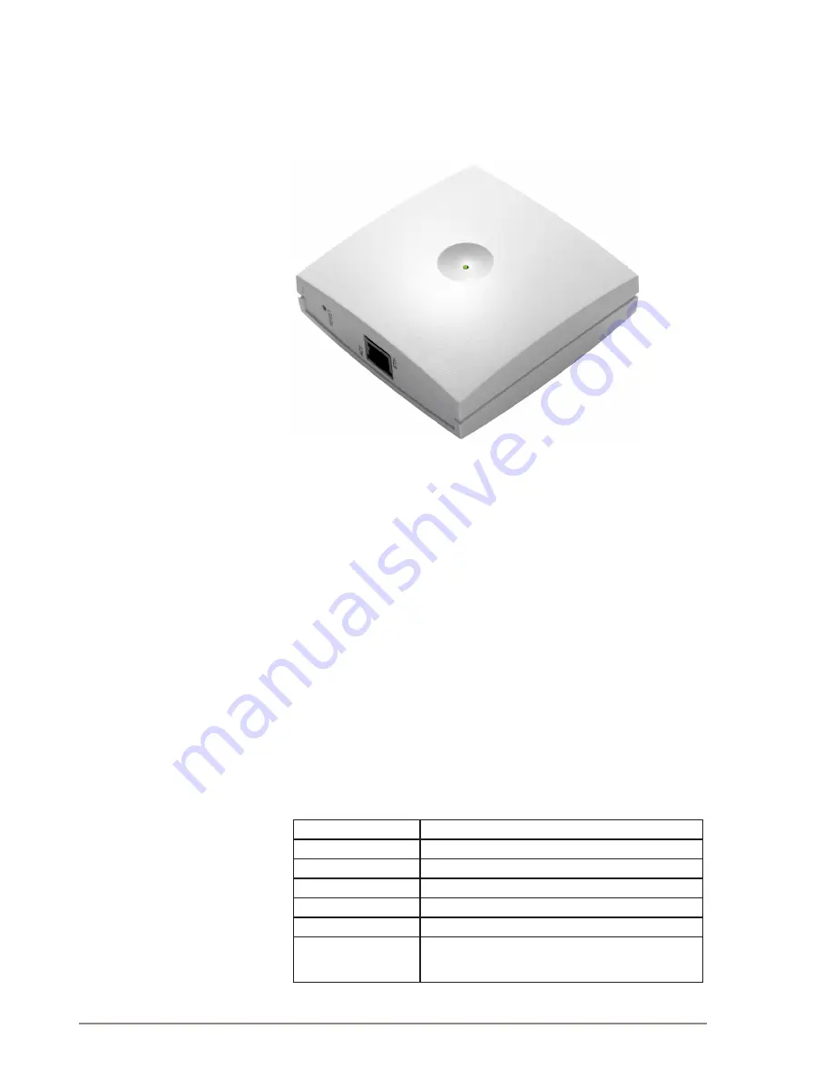
5.1.3 Base Station Appearance and Components
The base station front cover has a LED that indicates the operating
status of the unit
Figure 13 Base Station - Front view
The base station faceplate includes a Reset Button, a LINK/Activity
Indicator, and an Ethernet Port (Power supply through PoE).
For more information on the Reset button, refer to “Resetting the Base
Station Hardware”.
5.1.4 Base Station LED Indicators
5.1.4.1 Front Cover
The base station front cover has one indicator describing the base
station faults and failures. The indicator is off when the base station is
not powered. The LED flashes when the base station initializes. The
indicator is on when the base station is operating.
Table 5 LED Indicator Description - Front Cover
LED Indicator
Meaning
Steady green
OK and idle
Slow green flashing
OK and active voice call
Fast green flashing
Active, in operation with max. active connections (busy)
Fast red flashing
Error
Steady red
Reset/shutdown in progress
Steady red for 5
seconds followed by fast
red flashing
Reset to factory settings
LED


