


AC70 VC CONTROL FREQUENCY INVERTER MANUAL
FUNCTION PARAMETER DETAILED SPECIFICATION
97
3. If need start motor in reverse direction, press the K1 first, and press SB3 immediately.
5: 3 wire control mode 4
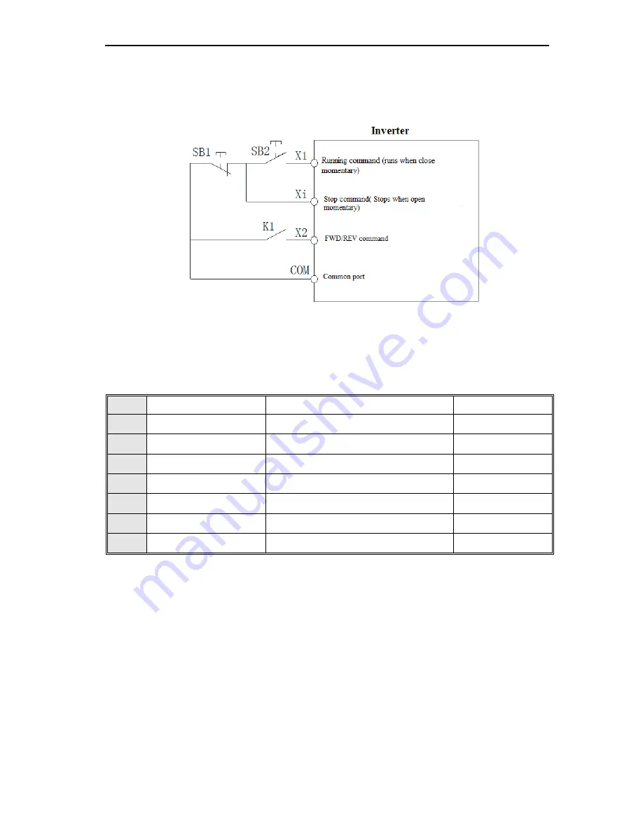
3 wire running control terminal (X1) uses for stop command terminal, running
command is determined by forward running terminal X1 (forward running), direction is controlled by reverse running
terminal X2( reverse running), and direction will be change after every Xi is activated. Every starts running based on
last direction memorized. 3 wire running control terminal X1 for effective input.
Tip: SB1 is a normal stop button, SB2 is a normal open button. K1 used for running direction selection
button. Xi is multi-function terminal (X1-X6) which have been programmed for 3 wire running control
terminal.
LED ten digit: Reserve
LED hundred digit: Reserve
LED thousand: Reserve
F-09
1 step speed setting 1X
Rang:0.00Hz-upper limit frequency
Default: 30.00Hz
F-10
2 step speed setting 2X
Rang:0.00Hz-upper limit frequency
Default:25.00Hz
F-11
3 step speed setting 3X
Rang:0.00Hz-upper limit frequency
Default: 40.00Hz
F-12
4 step speed setting 4X
Rang:0.00Hz-upper limit frequency
Default: 50.00Hz
F-13
5 step speed setting 5X
Rang:0.00Hz-upper limit frequency
Default: 50.00Hz
F-14
6 step speed setting 6X
Rang:0.00Hz-upper limit frequency
Default: 40.00Hz
F-15
7 step speed setting 7X
Rang:0.00Hz-upper limit frequency
Default: 25.00Hz
F-16
8 step speed setting 8X
Rang:0.00Hz-upper limit frequency
Default: 10.00Hz
Uses for setting program running and multi-step speed running frequency separately.
Multi-step speed control has the priority only next to the jog function. If users choose the multi-step speed running
mode, they need to set four multi-function input terminals as multi-step control terminal. ON/OFF between the four
terminals and (COM) determine the running speed steps. Its running and direction is controlled by the running
signal and direction given by the running control command channel
[E-01]
. And its acceleration, deceleration time is
controlled by the acceleration, deceleration time 1 in default. Or specifies the particular acceleration, deceleration
time by
[F-01]-[F-06]
parameters setting.
Swing frequency control need to configure the
[F-09]
and
[F-10]
, refer to
[H-51]
parameters for the requirement
setting of
[F-09]
and
[F-10]
. Inverter will appear fault alarm “Err5” if wrong setting.
Tip 1. Multiple step speed running don’t limited by lower limit frequency, but subject to upper limit frequency.
2. Output of program running is subject to limit by upper and lower limit frequency. Inverter will run with lower limit
frequency when the frequency given less than lower limit frequency.