AC70 VC CONTROL FREQUENCY INVERTER MANUAL
FUNCTION PARAMETER DETAILED SPECIFICATION
85
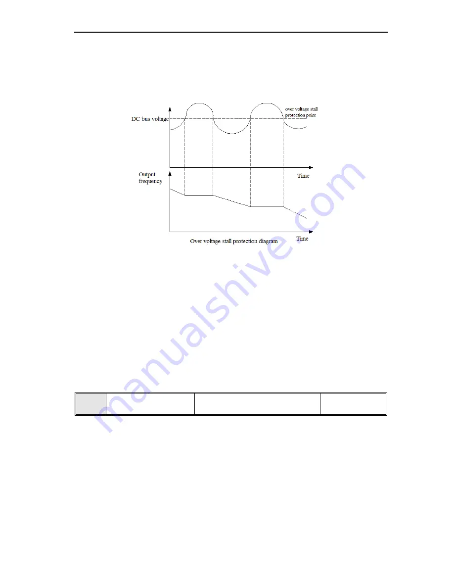
During the inverter deceleration, the energy generated by motor feedback to inverter inside due to load inertia effect,
which will cause the voltage of inverter over the maximum voltage threshold. The over voltage protecting occurs if
without any measure. When overvoltage protection is activated, the inverter deceleration stops (output frequency
stop descend) when detecting the DC bus voltage over
[E-53]
setting, deceleration only allow to continue until the
DC bus voltage is lower than the protective value.
Note: It will cause the stop time from deceleration given to stop to be longer if the stall protection is active.
LED ten digit: Output phase missing protection
0: Disable 1: Enable
Used for detecting if output wiring missing when inverter power on, if there are any output phase missing, the Err2
occurs, fault output terminal will be activated.
LED hundred digit: Input phase missing protection
0: Disable 1: Enable
Inverter performs phase missing detecting for 3 phase AC input, if any phase missing, Err1 will occurs, and stop
output. Motor will carry out free stop, the fault output terminals will be activate.
LED thousand digit: Inverter overload, over heat protect mode selection.
0: Free stop 1: running with current limit
This parameter will determine the protection mode when overload, over heat occurs.
Free stop means that output of inverter stop immediately, and active ‘OL2’and ‘OH’ fault alarm.
The running with current limit is that inverter running is based on output current limit. If the current over the current
limit value, the output frequency will be decreased to reduce the load current. The output terminal
[F-30-F-32]
can
be used to output pre-alarm signal when overload happens.
Current limit value during overvoltage and overheat=rated current ×100%
E-50
Coefficient value of
electronic thermal
Range:30%-120% Default:0%
Motor will generate heat seriously in a long time overload running. This parameter is used to set coefficient of
thermal relay of motor in inverter. When the rated current of motor is equal to rated current of inverter, the value can
be set 100%, when the rated current of motor can’t match the rated current of inverter, this parameter value can be
set for motor overheat protection properly.
The factory default setting of overload capacity of inverter as follows:
G type: 150%× rated current for 1 minute.
F type: 120%× rated current for 1 minute.
The parameters setting value can follow below formula:
Coefficient value of electronic thermal=rated current/ rated output current of inverter
Note: This function would fail when one inverter drives multiple motors in parallel. Please install the
thermal relay before motor input to protect motor effectively


