


AC70 VC CONTROL FREQUENCY INVERTER MANUAL
FUNCTION PARAMETER DETAILED SPECIFICATION
70
3: Terminal AS analog current signal 4-20mA
Main frequency given is determined and modified by ( AS)
analog current input; Regarding the relationship between input analog and frequency, filter time of input analog,
Please refer to parameters in detail
[F-50, F-51, F-52, F-56, F-57, F-58]
.
4: Terminal VS2 analog voltage -10-10V
Main frequency given is determined and modified by control terminal
VS2 analog input, Regarding the relationship between input analog and frequency, filter time of input analog,
Please refer to parameters in detail
[F-44, F-45, F-46, F-47, F-48, F-49, F-56F, -57, F-58]
5: Pulse train signal
Main frequency given is determined and modified by control terminal (PUL) analog input,
Regarding the relationship between input analog and frequency, please refer to parameters in detail
[F-53, F-54,
F-55, F-56, F-57, F-58]
6: RS485 communication port
Main frequency given is determined by receiving signal of (A+) and (B-) of
RS485 communication port.
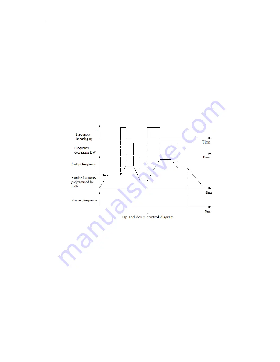
7: Up and Down control
Main frequency given is determined by increasing UP and decreasing (DOWN) terminal
connecting or disconnecting( ON/OFF) with COM terminal; each of multi- terminal ( X1-X6) can be programmed by
frequency UP terminal and DOWN terminal, refer to
[F-01-F-06]
in detail; Initial frequency of up and down terminal
control can be configured, please refer to parameter
[F-07]
LED ten digit option and
[F-70]
.
The acceleration and deceleration time of UP and Down control running is determined by acceleration/ deceleration
time 1
[E13-E-14]
setting; The rate of speed change of Up and Down terminal is determined by acceleration/
deceleration time 2
[F-24-F-25]
setting.
8: General PID operation
Select it use to set up general PID close loop control system. When it has been applied,
the [H-16] present setting value can be modified by up and down arrow button of keypad.
9: Constant pressure PID control
It can be used to set up constant pressure PID control ( constant pressure
water supply system etc) close loop system, the
[H-16]
present setting value can be modified by up and down
arrow button of keypad.
10: Program running
Main frequency given and rotation direction are configured by inverter’s inner simple PLC
process control. Up to 8 steps speed control is available, more detail refer to
[E-13, E-14, F-09-F-16, F-24-F-29,
H-32-H-51].
Run and stop command of program running determined by present setting value of running control command
selection.
When a step running time is set to 0, it means it will skip over this step when perform the program running. It is
easy to set up the steps required of program running.
When
[E-46]
parameter is set to 2 for forbidding reverse running, inverter will be run at 0 speed when arriving to a
step which have been set to reverse running.
Program running and multi-step speed operation are designed to achieve inverter variable-speed operation under a
certain laws. Among the multi step operation, multi step speed switch over and rotation direction changing are
achieved through the different combinations of external multi-step speed terminal with COM terminal ON and OFF.
Multi step frequency, operation time, rotation direction can be defined by function parameters. Multi step speed
control can be defined by each multi-function terminal, Please refer to
[F-01-F-06]
parameters.
11: Swing frequency run
Output frequency periodically changes by pre-set decel & accel time. This function